








What Gearbox Efficiency Loss Is Acceptable in an Automation Line?
How much gearbox efficiency loss is acceptable in an automation line? There is no single percentage that fits every machine, but a practical answer is this: a gearbox should not be accepted merely because it can transmit the required torque. Its losses must also be low enough that heat, energy consumption, positioning stability, lubricant condition, and service life remain under control throughout the real duty cycle.
For many continuously running automation systems, engineers will usually treat efficiency above roughly 90% as a reasonable starting point for a conventional speed reducer. High-efficiency helical and well-matched planetary gearboxes are often expected to perform above that level under their intended operating conditions. Worm gearboxes can be lower, sometimes substantially lower at high reduction ratios, yet may still be acceptable where self-locking behavior, compact layout, low speed, or intermittent duty matters more than energy efficiency.
The important distinction is between a loss that is technically tolerable and a loss that is economically or thermally sensible. A 5% loss in a lightly loaded indexing unit may have little practical consequence. The same 5% loss in a conveyor drive operating two or three shifts per day becomes a permanent heat source and an operating-cost issue. In automated production, small losses rarely stay isolated; they influence motor sizing, cabinet ventilation, lubricant aging, and sometimes cycle-time consistency.
Efficiency Is Not Just a Nameplate Number
Gearbox efficiency is the ratio of mechanical output power to mechanical input power. The difference is converted mainly into heat through gear meshing friction, bearing drag, seal friction, lubricant churning, and—in some designs—sliding contact between gear teeth. That sounds straightforward, but catalogue efficiency values are often based on defined speed, torque, lubricant, temperature, mounting position, and reduction ratio. A gearbox used far below its rated torque or at very low speed may not produce the same result seen in a published rating.
This is why a power calculation alone can mislead a design team. A gearbox can appear efficient at nominal load but spend most of its working life accelerating, decelerating, dwelling, or operating with repeated reversals. Servo-driven pick-and-place axes are a good example. Their concern may be less about steady-state energy loss and more about backlash, torsional stiffness, reflected inertia, repeatability, and heat generated during aggressive cycling.
Conversely, a packaging conveyor, pallet-transfer line, mixer feed system, or bottling machine may run for long periods at relatively stable speed. In those applications, continuous losses deserve closer scrutiny because every lost watt becomes thermal load for hours at a time.
A Practical Way to Judge “Acceptable” Loss
Rather than beginning with a fixed efficiency target, begin with the consequence of the loss. The basic relationship is simple:
Power loss = input power × (1 − gearbox efficiency)
If a gearbox receives 10 kW and operates at 95% efficiency, about 0.5 kW is dissipated as heat. At 85% efficiency, the loss rises to about 1.5 kW. That additional 1 kW may be unimportant in an open, cool environment with intermittent production. In a compact guarded machine, a washdown enclosure, or a hot plant area, it can materially change the thermal picture.
A useful engineering review normally considers four questions:
- Will the calculated loss push gearbox oil, bearings, seals, or adjacent equipment beyond their intended temperature range?
- Does the loss force a larger motor, drive, cooling arrangement, or electrical infrastructure than the machine otherwise needs?
- Is the system expected to run long enough for energy waste to outweigh the lower purchase price of a less efficient gearbox?
- Will gearbox heat affect accuracy, lubrication life, safety guarding, or the reliability of nearby sensors and cables?
When the answer to any of these is yes, the “acceptable” loss is probably lower than the initial design assumed.
Gearbox Type Changes the Conversation
Helical gearboxes are widely used where steady transmission efficiency and durable continuous operation are priorities. Their rolling and meshing characteristics generally make them a strong fit for conveyors, material handling, process equipment, and many general automation drives. A properly selected helical unit can be efficient, but oversizing it excessively may introduce unnecessary churning and bearing losses at low load.
Planetary gearboxes are often selected for compactness, torque density, and motion-control performance. They are common in robotics, rotary tables, packaging equipment, and servo-driven axes. Their efficiency can be very good, but the exact outcome depends on the number of stages, preload, lubricant, input speed, and load profile. A three-stage planetary unit may solve a ratio problem while adding more loss than a lower-ratio arrangement with a different motor strategy.
Worm gearboxes deserve a more nuanced judgment. They can be entirely appropriate for certain actuators, gates, light-duty positioning systems, and equipment requiring particular mounting flexibility. But because worm drives rely more heavily on sliding contact, their efficiency is sensitive to ratio, lubrication, material pairing, and operating conditions. A worm reducer selected only on output torque can become a persistent thermal problem when placed on a long-running conveyor.
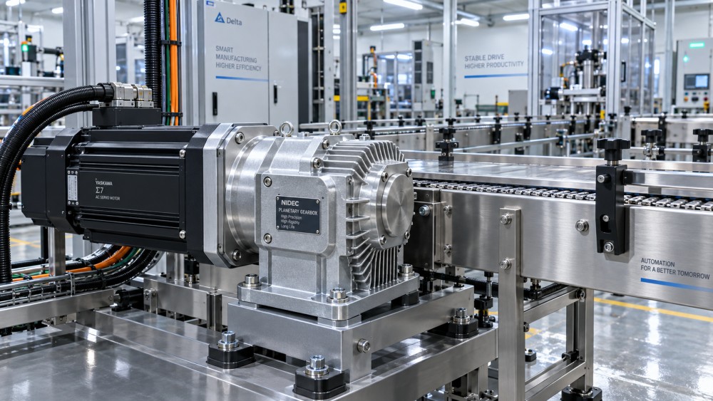
Bevel-helical and right-angle solutions often offer a better efficiency route than worm gearing where a 90-degree drive is required and continuous duty is significant. The right choice still depends on space, shaft orientation, shock loads, maintenance access, washdown exposure, and the need for backdrivability or holding torque.
The Hidden Cost Is Usually Temperature
Field troubleshooting often starts when a gearbox feels hot, leaks around a seal, or requires lubricant changes more frequently than expected. In many cases, the root cause is not a defective unit but an incomplete duty-cycle assessment. The reducer may have been sized for torque while its thermal capacity was never checked against actual input speed and ambient conditions.
High oil temperature accelerates lubricant oxidation and can reduce film strength. Seal materials, bearings, and gear surfaces are then exposed to conditions that shorten useful life. Heat also changes dimensions. On a high-precision automation axis, thermal growth can affect alignment and repeatability even before a mechanical failure is visible.
Do not assume that a larger gearbox automatically solves this. A larger housing may dissipate more heat, but increased oil volume, drag, and inertia can create other compromises. The better approach is to compare the vendor’s thermal rating with the installed duty cycle, then verify actual operating temperature during commissioning. This is particularly important after a line-speed increase, a motor replacement, or a change in lubricant specification.
Load Profile Matters More Than Average Load
Average torque can hide damaging peaks. A carton erector may run at a modest average load yet impose repeated shock torque at each mechanical stop. A robotic cell may have low average power draw but demand sharp acceleration and deceleration dozens of times per minute. These conditions affect gear tooth loading, bearing life, and heat generation differently from a smooth, steady conveyor.
For this reason, acceptable loss should be assessed alongside service factor, peak torque, starts per hour, reversing frequency, and inertia ratio. A gearbox operating at 92% efficiency under steady torque may be a sound choice. The same nominal efficiency tells little about suitability if the unit is repeatedly exposed to overload, rapid reversals, or poor alignment.
There is also a common low-load trap. Some automated lines are deliberately designed with large torque margins, then run most of the time well below the gearbox’s favorable efficiency zone. This may be justified for reliability, but it should be intentional. Oversizing can increase upfront cost and may not deliver the expected energy performance.
What to Ask Before Approving a Gearbox
A useful gearbox review should go beyond “What is the rated efficiency?” Ask whether the value applies to the proposed ratio and stage count; whether it is measured at nominal torque or another condition; and how it changes with speed, lubricant viscosity, or temperature. For variable-speed drives, ask for the expected operating envelope rather than a single-point figure.
It is also worth checking the whole powertrain. Belt tension, chain condition, coupling alignment, bearing condition, and motor-drive tuning can consume more energy than teams expect. Replacing a reducer with a more efficient model will not cure a line where a misaligned coupling or overtightened chain is generating its own losses.
During commissioning, record input current, housing temperature, ambient temperature, output speed, and observed duty cycle. These basic observations are often more useful than a generic efficiency assumption. If a gearbox runs noticeably hotter after a process modification, investigate before treating it as normal wear.
A Better Decision Than Chasing the Highest Efficiency
The best gearbox is not always the unit with the highest published efficiency. In automation, the correct choice balances energy loss with torque capacity, positional behavior, installed space, lubrication needs, contamination risk, maintenance access, and expected operating hours. A very efficient reducer that cannot handle the machine’s peak reversals is not a good solution; neither is a robust reducer that quietly wastes enough energy to overheat its enclosure.
For decision-makers comparing transmission options across plants or suppliers, technical intelligence should connect tribology, material selection, load behavior, and lifecycle economics rather than treating them as separate purchasing categories. This is the kind of component-level view supported by the Global Precision Components & Motion Matrix (GPCM), where power transmission analysis is considered alongside bearing behavior, lubrication conditions, supply-chain factors, and evolving automation demand.
In practical terms, gearbox efficiency loss is acceptable when it remains within the thermal and economic limits of the actual line—not the simplified calculation sheet. If the line runs continuously, operates in a hot enclosure, or depends on precision motion, treat every percentage point of loss seriously. If duty is intermittent and the mechanism has other priorities, a lower-efficiency arrangement may still be the right engineering choice, provided its heat and maintenance implications have been checked rather than assumed away.
Related News
- How to Assess Power Transmission Quality Before Failures Reach the Production LineOct 13, 2026Power transmission quality assessment made practical: detect vibration, heat, lubrication, alignment, and backlash issues before they disrupt production.
- Buying Power Transmission Component Castings: Which Inspection Records Matter Most?Oct 12, 2026Power transmission component castings demand traceable inspection records. Learn which material, dimensional, NDT, and repair documents protect quality and reliability.
- Power Transmission Component Casting Defects That Shorten Gearbox Service LifeOct 11, 2026Power transmission component casting defects can trigger gearbox leaks, vibration, and bearing failure. Discover inspection priorities and repair-or-replace guidance.
- What Gearbox Efficiency Loss Is Acceptable in an Automation Line?Oct 14, 2026How much gearbox efficiency loss is acceptable in an automation line? Learn practical benchmarks for heat, energy costs, duty cycles, and gearbox selection.
Related News
- 00
0000-00
How to vet North American fluid dynamics engineering firms for CFD - 00
0000-00
How to qualify a semiconductor equipment parts supplier for traceability - 00
0000-00
Does higher hardness improve heavy equipment abrasion resistance? - 00
0000-00
How to choose high-impact wear materials for mill liners - 00
0000-00
Which fluid power components for pneumatics suit high-cycle automation?
Power Trans Designer
Strategic Intelligence Center