








Power Transmission Component Casting Defects That Shorten Gearbox Service Life
A hidden casting flaw in a gearbox housing, gear blank, or coupling can accelerate wear long before visible failure occurs.
For aftermarket maintenance teams, understanding power transmission component casting defects is essential when diagnosing vibration, misalignment, lubrication loss, and premature bearing damage.
The practical question is not simply whether a casting contains imperfections, but whether those imperfections affect load paths, sealing surfaces, dimensional stability, or fatigue resistance.
A small cosmetic pit may be harmless. A shrinkage cavity near a bearing bore, however, can turn an otherwise routine repair into another gearbox failure.
This guide explains the casting defects most likely to reduce gearbox service life, their field symptoms, inspection priorities, and repair-versus-replacement decisions.
Why Casting Quality Matters During Gearbox Repair
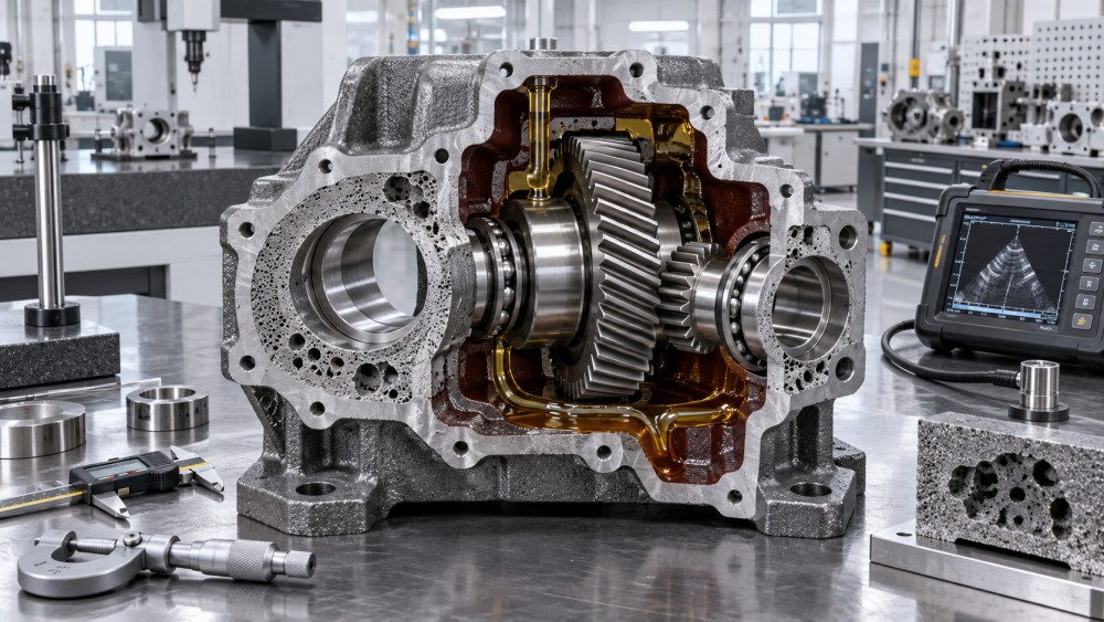
Gearboxes depend on stable geometry. Shafts, bearings, gears, seals, and couplings must remain aligned while transmitting torque through changing loads and temperatures.
Cast components are often selected because they provide complex shapes, vibration damping, machinability, and economical production for housings, gear blanks, covers, and brackets.
However, a casting defect can remain dormant until machining removes supporting material, cyclic loading initiates a crack, or thermal cycling opens a leakage path.
Maintenance teams often replace bearings, seals, and gears without fully investigating why the original components failed earlier than expected.
That approach can miss the structural cause. A defective housing may repeatedly overload replacement bearings despite correct lubricant, assembly torque, and installation procedures.
For service personnel, the key value of casting inspection is risk separation. It helps distinguish a reusable component from one that will compromise the repair.
Inspection should focus first on areas that control mechanical position: bearing seats, shaft bores, gear hubs, mounting faces, oil galleries, and sealing joints.
These locations transfer force or preserve operating clearance. Defects elsewhere may matter less, depending on component duty, material grade, and safety requirements.
Porosity: The Defect Most Often Linked to Leaks and Weak Sections
Porosity consists of small voids trapped within or near the surface of a casting. It can result from gas entrapment, dissolved gas, poor venting, or solidification shrinkage.
In power transmission component casting, porosity becomes serious when it reaches machined surfaces or joins together beneath a highly stressed section.
Gas porosity commonly appears as rounded, smooth cavities. Shrinkage porosity is often irregular, interconnected, and concentrated near thick-to-thin section transitions.
Gearbox housings are especially vulnerable around bearing bosses, rib intersections, oil channels, drain ports, and thick mounting lugs.
After machining, pores can expose a path between the internal oil cavity and the exterior surface. The result may look like a failed gasket or seal.
Before blaming the sealing system, clean the area, apply a suitable developer or leak-detection method, and trace the actual origin of oil seepage.
Porosity around bearing bores can also reduce local stiffness. Under load, the bore may distort slightly, changing bearing preload, clearance, or contact distribution.
Symptoms can include elevated bearing temperature, repeated outer-race fretting, unexplained vibration, or uneven wear patterns on rolling elements.
Minor isolated pores outside stressed and sealed surfaces may be acceptable under the original manufacturer specification. Field repairs should not assume this automatically.
Welding, impregnating, or applying sealant may stop leakage, but these methods do not restore original fatigue strength or bore stability.
When porosity is near a bearing seat, gear hub, pressure boundary, or mounting interface, replacement is usually the more defensible long-term decision.
Shrinkage Cavities Can Create Hidden Fatigue Failure Sites
Shrinkage cavities develop when molten metal cannot feed a region adequately as it contracts during solidification. They are particularly common in heavy sections.
Unlike superficial pinholes, internal shrinkage can substantially reduce effective cross-sectional area in a loaded housing, hub, flange, or gear blank.
The danger increases where geometry already concentrates stress, such as sharp fillets, keyway zones, flange roots, tooth rims, and bearing support webs.
During operation, cyclic torque and vibration repeatedly load these regions. A cavity edge can act as a stress raiser and initiate a crack.
Maintenance teams may first notice a faint oil line, rust bleed, or dark stain at an exterior surface. These marks can indicate crack propagation.
Other warning signs include mounting bolts losing preload, coupling alignment changing after warm-up, or vibration increasing only under transmitted load.
Visual inspection alone rarely confirms internal shrinkage. Dye penetrant testing can reveal connected surface cracks, but it cannot reliably map hidden cavity depth.
Ultrasonic testing may help on sufficiently thick, accessible sections. Radiographic inspection can provide better information when internal discontinuity location is critical.
For a critical gearbox, compare the inspection result with operating duty. Shock loads, reversing torque, high cycle counts, and elevated temperatures lower the acceptable risk.
A cracked or heavily shrinkage-affected load-bearing casting should not be treated as a cosmetic repair issue, even when the gearbox remains operational.
Inclusions and Sand Defects Can Damage Machined Functional Surfaces
Nonmetallic inclusions are foreign particles trapped in the metal during pouring. They may include slag, oxides, refractory fragments, sand, or mold-coating debris.
Sand inclusions and sand wash defects are particularly relevant in cast iron housings and complex castings with internal oil passages.
When machining exposes an inclusion, the affected surface may contain soft spots, voids, irregular grooves, or areas with poor surface finish.
On a bearing bore, this can prevent uniform contact between the outer race and housing. The bearing may creep, fret, or transfer heat poorly.
On a gear blank or coupling hub, inclusions can weaken the bore-to-hub area, especially near keys, splines, shrink fits, or interference fits.
In oil-wetted components, loose sand or inclusion fragments can become abrasive contamination. They may circulate until a filter captures them or damage sensitive surfaces.
During teardown, inspect oil sediment and magnetic plugs carefully. Nonmagnetic grit may indicate casting residue, external contamination, or a failed internal coating.
Do not assume all debris came from gear wear. Compare particle shape, hardness, color, and quantity with the damaged component surfaces.
Bores with isolated shallow imperfections may be repairable through approved sleeving, machining, or controlled metal restoration. Dimensional requirements remain decisive.
If repair changes interference fit, concentricity, oil clearance, or heat-transfer behavior, the component must be evaluated as a redesigned condition, not a simple restoration.
Cold Shuts and Misruns Can Become Crack Paths Under Cyclic Torque
A cold shut occurs when separate streams of molten metal meet but fail to fuse completely. A misrun occurs when metal freezes before filling the mold.
These defects often form thin, seam-like discontinuities. They can be mistaken for surface scratches, grinding marks, casting parting lines, or harmless visual irregularities.
In a power transmission component casting, a cold shut is concerning when it crosses a structural wall, flange, rib, hub, or attachment point.
The incomplete fusion acts like a pre-existing crack. Under cyclic loading, it can extend without the large overload event normally associated with fracture.
Gearbox covers are not always structurally critical, but defects around fastener bosses can reduce clamping force and produce recurring gasket leakage.
Housing defects near mounting feet can allow minute movement against the machine base. This can lead to soft-foot conditions and shaft alignment changes.
Use strong directional lighting after thorough cleaning. A cold shut may become clearer when the surface is lightly polished or examined with magnification.
Dye penetrant testing is useful for nonporous materials where the discontinuity reaches the surface. Magnetic particle inspection is effective for ferromagnetic castings.
Any confirmed crack-like indication around a bearing support, torque reaction point, or coupling guard attachment deserves engineering review before returning equipment to service.
Grinding away the visible line is not proof of removal. The defect may continue below the surface or reappear after thermal and mechanical cycling.
Distortion and Residual Stress Can Defeat Accurate Assembly
Not all damaging casting defects are voids or cracks. Distortion and residual stress can shorten gearbox life by changing dimensions after machining or during operation.
Large cast housings cool unevenly. Without appropriate process control and stress relief, internal stresses may remain locked into the component.
Once the casting is machined, mounted, heated, or heavily loaded, those stresses can redistribute. Bearing center distances and bore roundness may change.
For helical, bevel, and worm gearboxes, small geometric changes can alter tooth contact patterns and dramatically increase localized gear loading.
Common field clues include correct initial backlash followed by rapid noise increase, unusual tooth-face wear, recurring seal failure, or unexplained bearing preload changes.
Check housing mounting faces for flatness and inspect bore geometry at several clock positions. Measure both diameter and roundness where equipment permits.
Also compare bearing bore center distance, shaft centerline relationship, and cover-to-housing alignment against manufacturer limits or reliable baseline measurements.
Torqueing a distorted cover can pull a bearing outer race out of alignment. The damage may appear later as edge loading or cage distress.
Do not rely only on nominal bore diameter. A bore can meet its average diameter requirement while still having ovality or taper beyond acceptable limits.
Where distortion is suspected, inspect the complete assembly condition. Separate component measurements can miss deformation created by bolting, mounting, or thermal growth.
Machining Exposure Often Turns a Latent Defect Into a Service Problem
Many casting defects become operational problems only after secondary machining. Material removal can uncover pores, inclusions, thin walls, and local weakness.
This is why post-machining inspection matters as much as foundry inspection for aftermarket repair decisions and replacement-component acceptance.
Critical machined features include bearing bores, seal lands, gear bores, keyways, spline roots, threaded ports, mounting pads, and gasket faces.
On seal lands, even small surface discontinuities can create spiral leakage paths. On threaded ports, porosity can cause recurring leakage despite correct thread sealant.
On bearing seats, defects can alter fit retention. A loose outer race can spin in the housing, generating heat and destroying the bore.
On gear blanks, machining may reveal subsurface discontinuities near the tooth root or hub. Both areas experience high cyclic stress during torque transmission.
Repair technicians should record defect location relative to functional geometry, rather than describing every indication only by its visible size.
A two-millimeter pore on an external rib may be insignificant. The same pore at the edge of a bearing shoulder may be unacceptable.
Photographs with scale, bore measurements, leakage evidence, and operating history create a stronger basis for warranty discussions and replacement recommendations.
A Practical Inspection Sequence for Aftermarket Maintenance Teams
A disciplined inspection sequence prevents teams from spending labor on a gearbox that contains an unserviceable structural casting.
Start with service history. Document duty cycle, overload events, lubricant condition, previous bearing replacements, leakage points, vibration trends, and temperature records.
Next, clean the component thoroughly. Oil, paint, corrosion products, and old sealant can conceal casting cracks, porosity, and machining-related damage.
Perform a visual inspection under strong light. Examine bearing bores, mounting feet, ribs, bosses, gear hubs, sealing faces, and oil passage areas.
Measure functional features before disassembly destroys evidence. Record bore size, roundness, taper, shaft fit condition, gear backlash, and mounting-face flatness.
Select non-destructive testing based on material and suspected defect. Dye penetrant identifies surface-breaking flaws, while magnetic particle testing suits ferromagnetic materials.
Use ultrasonic or radiographic methods when internal shrinkage or hidden cracking could affect a critical load path. Consider specialist support for high-value equipment.
Then assess the defect against actual service demands. Higher torque, reversing loads, frequent starts, contamination exposure, and safety consequences require stricter judgment.
Classify findings into three practical groups: monitorable cosmetic conditions, repairable functional defects, and replacement-required structural or pressure-boundary defects.
Document the decision and evidence. A clear inspection record protects maintenance quality and helps identify recurring supplier, design, or operating issues.
Repair or Replace? Use Function, Location, and Consequence
The right decision is rarely based on defect appearance alone. Its location, depth, orientation, component material, loading, and consequence of failure are more important.
Cosmetic surface roughness away from stressed or sealed regions may remain in service after confirming that no crack, leakage path, or dimensional concern exists.
Localized damage on a noncritical machined surface may be repairable when an approved process restores dimensions, surface condition, and mechanical retention.
Repair becomes less appropriate when defects affect bearing seats, gear tooth support, spline hubs, torque arms, mounting feet, or oil containment boundaries.
Weld repair requires particular caution. Heat input can create distortion, hard zones, residual stress, or cracking, especially in cast iron components.
Any welded gearbox housing should be evaluated for material compatibility, preheat requirements, post-repair machining, pressure integrity, and dimensional verification.
Replacement is normally justified when a defect threatens alignment, fatigue life, pressure containment, or the integrity of a critical rotating component.
The apparent savings from retaining a questionable casting can disappear quickly after repeat downtime, damaged gears, contaminated lubricant, or unplanned production interruption.
Conclusion: Inspect the Casting Before Rebuilding the Gearbox
Power transmission component casting defects are not merely foundry-quality concerns. They directly influence gearbox alignment, lubrication retention, bearing life, and fatigue reliability.
For aftermarket maintenance personnel, the highest-value inspections concentrate on bearing supports, load-bearing hubs, mounting interfaces, machined sealing surfaces, and oil-containing walls.
Porosity, shrinkage cavities, inclusions, cold shuts, distortion, and residual stress each produce different warning signs, but all can create repeat failures.
Use visual examination, dimensional measurement, operating history, and suitable non-destructive testing together. No single method provides a complete diagnosis.
Most importantly, judge every indication by function and consequence. A defect becomes serious when it compromises geometry, load transfer, sealing, or long-term fatigue resistance.
That disciplined approach helps maintenance teams make repair decisions that extend gearbox service life instead of simply postponing the next failure.
Related News
- Power Transmission Component Casting Defects That Shorten Gearbox Service LifeOct 11, 2026Power transmission component casting defects can trigger gearbox leaks, vibration, and bearing failure. Discover inspection priorities and repair-or-replace guidance.
- What to verify before choosing a chain drive systems supplierOct 01, 2026Chain drive systems supplier selection made easier: verify load analysis, standards, traceability, lubrication, quality control, and delivery reliability before buying.
- When does a low backlash transmission improve positioning accuracy?Sep 27, 2026A low backlash transmission improves positioning accuracy by reducing reversal error, enhancing settling, and supporting reliable precision motion.
- Component material comparison for wear resistance in moving partsSep 11, 2026Component material comparison for wear resistance: explore steel, bronze, polymers, ceramics, and composites to select reliable moving parts for real operating conditions.
Related News
- 00
0000-00
When do tighter tolerances justify precision manufacturing solutions for aluminum parts? - 00
0000-00
Power Transmission Component Casting Defects That Shorten Gearbox Service Life - 00
0000-00
Is a Higher Actuator IP Rating Necessary for Factory Environments? - 00
0000-00
How to build a product category guide for Latin American markets - 00
0000-00
When stainless steel industrial couplings are needed for corrosive fluids
Power Trans Designer
Strategic Intelligence Center