








A thermal interface can look correct on a drawing and still create a hotspot after assembly. A cold plate may sit flat at room temperature yet lose contact when clamped to a housing. A heat spreader may meet its nominal thickness while a shallow bow, rough tool marks, or a misplaced datum prevents the intended pressure field from developing. In these situations, heat-transfer performance is being limited not by the material specification alone, but by the way dimensional and geometric variation accumulates across the joint.
The central rule in precision thermal component production is that a tolerance matters when it changes the thermal path: contact area, interface pressure, conductive cross-section, fluid passage geometry, or the position of the heat source relative to the cooling feature. The most useful approach is therefore not to tighten every dimension. It is to identify the few tolerances that control thermal resistance under actual mounting load, temperature range, and assembly sequence, then assign inspection methods that can prove those conditions are being maintained.
Thermal performance is controlled by an assembled condition
Heat-transfer drawings often begin with individual part dimensions because those are easy to specify and inspect. The thermal system, however, operates only after multiple components are brought together: a semiconductor package, thermal interface material, spreader, cold plate, fasteners, seals, and sometimes a coolant manifold. Each element adds variation. A part that passes a standalone flatness check can still create poor contact if its mounting face is not parallel to the reference surface used during clamping.
This distinction is especially important when the assembly relies on a thin thermal interface material. A thick compliant pad may accommodate modest surface variation, although it introduces its own bulk thermal resistance. A thin grease layer, phase-change material, solder layer, or metallic interface is far less forgiving. Small gaps become significant because air trapped at an interface conducts heat poorly compared with the intended material path.
Technical evaluation should therefore begin with the functional stack rather than the manufacturing drawing alone. Ask:
- Where does heat enter the component, and what is the intended route out?
- Which surfaces must maintain intimate contact, and which merely provide mechanical location?
- What mounting load, fastener pattern, and tightening sequence establish the contact condition?
- Which dimensions change materially over the operating temperature range?
- Can a tolerance shift move a heat source away from a fin field, coolant channel, vapor chamber zone, or high-conductivity insert?
These questions separate dimensions that are visually important from dimensions that are thermally decisive.
Start with the interface, not the nominal part size
At a bolted thermal joint, surface flatness is usually more consequential than an isolated length or width tolerance. Flatness determines whether clamping load is distributed across the designed contact region or concentrated at a few high spots. Parallelism matters when two opposed mounting faces must transfer load through a defined stack. Surface profile can matter even more when a machined base must align with a localized source or a patterned thermal interface.
Roughness requires a more careful reading. A lower roughness value does not automatically produce lower thermal resistance. Extremely smooth surfaces may be difficult or costly to produce, and a particular interface material may require a surface texture that promotes wetting, retention, or mechanical anchoring. The relevant question is whether the surface topography is compatible with the selected interface material and applied pressure. Deep machining marks running across a narrow heat path, burrs around drilled holes, waviness from an unstable finishing process, or isolated dents near the heat source can be more harmful than an average roughness value suggests.
A useful specification distinguishes among several forms of variation:
Calling out a general flatness requirement across a large casting or plate can be misleading. The function may reside in a smaller central land beneath a device package. In that case, a local datum scheme and a localized flatness or profile control may protect performance more effectively than a severe global requirement that increases manufacturing difficulty without improving the active contact zone.
Datum selection determines whether inspection reflects real use
A recurring source of disagreement is a component that appears in tolerance during inspection but does not fit or perform consistently in the system. The problem is often datum selection. Production may hold the part from external edges, while assembly locates it from mounting holes, a shoulder, or a machined reference pad. Measurements tied to nonfunctional edges can give a false sense of control.
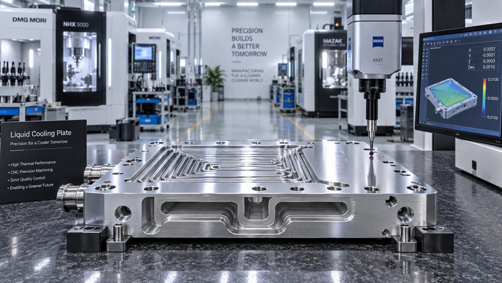
For thermal parts, datums should follow the load path and heat path where practical. Consider a liquid-cooled plate attached to a power module. The device mounting face may be the primary datum because it establishes contact with the heat source. The mounting-hole pattern may serve as a secondary datum because it sets clamp position and load distribution. A connector or manifold interface may need a third datum because its positional relationship affects assembly, sealing, and coolant routing.
That arrangement makes it possible to specify channel location, insert position, and opposite-face parallelism in terms of the surfaces that define functional behavior. It also reduces the risk that a component is measured perfectly in an orientation it will never experience during installation.
Do not confuse hole size with clamp control
Fastener holes influence thermal performance through more than simple fit. Oversized or misplaced holes can allow a component to shift relative to the heat source. Hole perpendicularity can alter washer seating and produce a biased load. Counterbore depth affects fastener engagement and may reduce local wall thickness near a coolant passage. Threaded holes placed too close to a thermal land can distort that land during machining or under tightening load.
Where mounting load is critical, the evaluation should consider the complete fastening arrangement: screw geometry, washer or flange contact, torque method, friction variation, joint stiffness, and tightening sequence. A precise thermal component cannot compensate for uncontrolled assembly loading. Conversely, overly tight geometric tolerances may be unnecessary if a compliant interface and a well-designed clamping system can absorb realistic variation.
Thermal expansion changes the tolerance picture
Room-temperature inspection is only one snapshot. When materials with different coefficients of thermal expansion are joined, their relative movement can change contact pressure and alignment as temperature rises or falls. Aluminum, copper, stainless steel, ceramics, polymers, and semiconductor packages do not expand at the same rate. The larger the span, temperature swing, and material mismatch, the more important this becomes.
A copper insert in an aluminum spreader illustrates the issue. The insert may be positioned accurately after machining, but differential expansion can generate local stress or alter the flatness of the working face. A rigid bond may preserve initial contact while transferring stress into the surrounding structure. A controlled clearance, compliant bonding layer, or feature geometry that allows strain relief may be preferable, depending on the operating environment and thermal requirement.
Thermal expansion also affects coolant-channel designs. Channel walls, cover plates, seals, and manifold interfaces move at different rates. A tolerance that is acceptable for a dry test assembly may cause seal compression to fall outside its intended range at temperature. The dimensional stack must include both minimum and maximum material conditions, the assembly temperature, and the expected operating range. Simply applying a generic machining tolerance to every feature does not capture this interaction.
Where tolerances should be tight—and where they should not
Unselective tightening drives cost, rejects, and inspection burden without necessarily reducing thermal risk. The better method is to rank features by functional sensitivity. A tight tolerance is justified when a small change produces a meaningful change in thermal resistance, fluid distribution, structural integrity, or repeatability of assembly load.
Features that often warrant closer control include:
- Flatness of the active thermal contact land beneath a concentrated heat source.
- Parallelism between surfaces that share a clamped interface stack.
- Position of coolant channels relative to high-flux zones, particularly where wall thickness affects conduction resistance.
- Wall thickness between a channel and the thermal surface when machining variation could create excessive resistance or insufficient structural margin.
- Location and depth of embedded heat pipes, conductive inserts, sensors, or cartridge heaters.
- Hole position and perpendicularity when the fastening pattern determines contact pressure distribution.
By contrast, exterior cosmetic surfaces, nonfunctional edge breaks, or dimensions remote from the heat path may accept broader limits. Their tolerances should still support manufacturability, handling, and assembly, but they should not consume the same process capability as a critical interface land merely because they appear on the same drawing.
A practical route from thermal model to production control
Thermal analysis can identify sensitive regions, but its conclusions must be translated into measurable production requirements. This is where many specifications become vague. A simulation may show that contact resistance dominates performance, yet the drawing only lists a generic finish and an overall thickness tolerance. The manufacturing team then receives no clear indication of which surfaces require process attention or how acceptance should be verified.
A more reliable sequence is to define the functional condition first. Establish the expected heat load distribution, mounting arrangement, interface material, contact pressure range, coolant parameters where applicable, and temperature envelope. Next, identify the geometric changes that most affect the modeled path. Convert those changes into tolerances tied to functional datums. Finally, choose inspection methods capable of detecting the relevant failure modes.
- Map the thermal path. Mark source locations, conductive transitions, interface zones, channel regions, and exit paths. This prevents a critical area from being hidden inside a broad general note.
- Build the assembly stack. Include parts, coatings, interface materials, fasteners, seals, and likely variation in compression or seating.
- Identify sensitivity. Determine whether performance is most affected by gap formation, reduced wall thickness, source offset, coolant imbalance, or differential expansion.
- Assign functional datums. Make inspection orientation correspond to the way the part is mounted and loaded.
- Specify the control method. Use profile, position, flatness, parallelism, thickness, surface texture, or a process requirement only when it connects to a known functional need.
- Validate the process, not just the first part. Confirm that finishing, fixturing, deburring, cleaning, joining, and inspection can repeatedly preserve the specified condition.
This sequence is particularly valuable when changing suppliers, moving from prototype machining to volume production, or revising a component for a different manufacturing route. A design may tolerate variation from a low-volume finishing process but react differently to milling, grinding, brazing, welding, die casting, or bonding at scale.
Inspection should reveal the defects that thermal tests may miss
A completed thermal test is useful, but it may not reveal why a part passed or failed. Results can also be influenced by fixture setup, interface application, sensor placement, ambient conditions, and mounting torque. Dimensional inspection provides traceability only when it targets the features that drive the thermal result.
Coordinate measurement is useful for positions, profiles, and datum relationships, while optical methods can reveal local form and surface defects over an active land. Surface instruments help distinguish roughness from longer-wavelength waviness. For internal channels, sectioning is destructive, so process-qualified methods may include validated tool offsets, controlled machining references, pressure testing for integrity, and non-destructive examination appropriate to the construction method. The correct method depends on whether the risk is a leak, a thin wall, a blocked passage, a shifted channel, or a distorted mating face.
Inspection frequency should follow risk rather than habit. A stable finishing operation for a noncritical exterior dimension does not require the same scrutiny as a lapped thermal land after a joining process that can introduce distortion. Sampling plans, in-process checks, and final inspection should be arranged around the moments when the critical condition can change.
Failure patterns that point back to tolerance control
Localized hot spots near one edge of a mounted device often suggest uneven contact, a tilted stack, insufficient clamp load, or a flatness problem concentrated in the active area. A broadly elevated temperature may instead point to excess interface thickness, an unintended material substitution, inadequate coolant flow, or a conductive path that is longer than assumed.
Performance drift after thermal cycling raises different questions. Inspect for relaxation in the interface material, loss of bolt preload, warpage caused by material mismatch, seal movement, or cracking and distortion around joined inserts. A component that initially performs well but becomes inconsistent after repeated operation is rarely explained by one nominal dimension alone; the interaction among materials, restraint, and assembly load must be examined.
When similar parts show wide thermal variation despite passing dimensional checks, review whether the inspection references the actual thermal land and whether surface form is being measured at a meaningful resolution. Average roughness, overall thickness, and a few point measurements can all pass while a localized bow or machining pattern prevents consistent contact.
Protecting performance through controlled change
Any production change that affects geometry, surface condition, material state, or assembly load deserves a thermal review. A different cutter path can alter waviness. A revised deburring operation can damage a sealing edge or leave raised material around a contact zone. Coating changes can alter thickness and interface behavior. A new joining cycle can distort a previously stable plate.
Precision thermal component production is strongest when drawing tolerances, manufacturing process controls, and thermal validation describe the same functional requirement. The goal is not the smallest possible number on every feature. It is a repeatable assembled condition: predictable contact, stable geometry through temperature, and a heat path that remains intact when the component is installed as intended.
Related News
- How to vet North American fluid dynamics engineering firms for CFDOct 13, 2026Searching for fluid dynamics engineering North America? Discover how to vet CFD firms, assess validation, and choose a partner for confident design decisions.
- Which sub-assembly tasks can industrial equipment suppliers handle?Oct 16, 2026What are common sub-assembly capabilities for industrial equipment suppliers? Explore mechanical, hydraulic, and electromechanical modules—and key checks to choose the right supplier.
- Does higher hardness improve heavy equipment abrasion resistance?Oct 14, 2026Does higher hardness improve heavy equipment abrasion resistance? Discover how wear mechanisms, toughness, and testing guide material choices to extend component life and reduce downtime.
- How to choose high-impact wear materials for mill linersOct 13, 2026Choose high-impact wear materials for mills with confidence. Compare liner toughness, wear resistance, and cost per tonne to improve reliability. Explore our practical selection guide.
Related News
- 00
0000-00
How to choose gear materials for high-load industrial gearboxes - 00
0000-00
How to choose engineering plastics for gears without lubrication - 00
0000-00
How to vet North American fluid dynamics engineering firms for CFD - 00
0000-00
How to qualify a semiconductor equipment parts supplier for traceability - 00
0000-00
Which sub-assembly tasks can industrial equipment suppliers handle?
Dr. Alistair Vaughn
Strategic Intelligence Center