








Weight reduction only creates value when it improves the behavior of the complete assembly. A lighter cover that does not affect motion, energy use, or load paths is rarely a priority. A lighter moving beam, pick-and-place arm, gantry member, satellite support structure, or transport fixture can be different: reduced moving mass can lower actuator demand, shorten settling time, improve handling safety, or free capacity elsewhere in the system.
That is where precision composite parts deserve serious consideration. Their advantage is not simply that carbon-fiber-reinforced polymer or glass-fiber-reinforced polymer weighs less than steel or aluminum. The useful property is specific stiffness: stiffness relative to mass. When fiber orientation, laminate thickness, section geometry, interfaces, and manufacturing tolerances are engineered as one system, composites can support stiff, lightweight structures that would be difficult to achieve with isotropic metals at the same mass.
The qualification matters. A composite component does not automatically retain the stiffness of the metal part it replaces. It must be designed around the load path, not copied from an existing drawing. Projects succeed when the team identifies where mass is driving a real system constraint and where the composite architecture can carry the required loads with predictable manufacturing quality.
Stiffness is a system requirement, not a material label
“Structural stiffness” is often used loosely, but it can mean several different things in an equipment project: resistance to bending, torsion, local crushing, buckling, vibration, or deformation at a mounting interface. A part may be highly resistant to bending in one direction and comparatively compliant in another. That is a defining feature of fiber composites.
Metals are generally treated as isotropic for practical design purposes: their properties are broadly similar in all directions. Fiber-reinforced composites are anisotropic. Fibers carry loads most effectively along their direction, while the resin matrix transfers shear between fibers, protects them, and helps resist loads transverse to the fiber direction. A laminate with nearly all fibers aligned along a beam’s length may offer excellent axial and bending performance, but it may not have enough torsional stiffness or through-thickness strength around bolted connections.
For that reason, a meaningful composite design begins with the load cases rather than a target material. The design team needs to establish:
- maximum static loads and their directions;
- repeated operating loads, including acceleration and deceleration cycles;
- allowable deflection at critical interfaces;
- torsional requirements that affect positional accuracy or alignment;
- natural-frequency targets where vibration, settling time, or resonance matters;
- local contact, clamping, impact, and pull-out loads at joints.
A useful engineering question is not “Can composites replace aluminum?” It is “Which deformation mode limits the assembly today, and can a composite structure improve that mode without creating a new weak point at the interface?”
Moving structures usually offer the clearest value
Precision composite parts are most compelling where structural mass moves repeatedly and directly affects performance. Robotic links, end-of-arm support members, high-speed inspection frames, automated handling arms, moving carriage structures, and lightweight aerospace or laboratory equipment supports are common examples. In these applications, the mass reduction can change more than the part weight.
Lower moving inertia can reduce the torque required for acceleration, potentially allowing changes in motor, gearbox, brake, or counterbalance selection. It can also reduce the kinetic energy that must be controlled during emergency stops. Where a servo system is limited by vibration or settling behavior, a well-designed composite member may improve the stiffness-to-mass balance enough to support faster motion profiles. The benefit is dependent on the entire dynamic system; it cannot be inferred from material density alone.
Long, slender structures are particularly relevant because bending stiffness depends strongly on section geometry. A hollow composite tube, box section, or sandwich panel can place material away from the neutral axis, where it contributes more effectively to bending resistance. Carbon-fiber skins combined with a lightweight core can create stiff panels for covers, platforms, and instrument enclosures when loads are distributed appropriately. In such cases, the structure’s geometry can matter as much as the fiber type.
For stationary structures, the case is narrower but still valid. Composite machine enclosures, metrology frames, optical supports, medical-device housings, and corrosion-exposed process equipment may benefit where low mass simplifies installation, reduces support steel, improves thermal behavior, or avoids corrosion-related maintenance. However, stationary machine bases carrying high cutting forces or demanding long-term geometric stability require a more cautious comparison. Cast iron, welded steel, mineral cast, and aluminum structures each bring different damping, thermal, cost, and integration characteristics. A low-mass composite solution is not automatically the best foundation for a high-load precision machine.
Applications where the material architecture solves a real problem
Robot arms and end-effectors. A lightweight link can reduce distal mass, which is especially important because the mass farther from a robot joint has a larger effect on joint torque and inertia. Carbon-fiber tubes and molded shells can be effective when the principal bending and torsional loads are known. The critical engineering work often sits at the ends: bearing housings, gearboxes, tool flanges, cable exits, and fasteners must transfer concentrated forces into a laminate that prefers distributed loading.
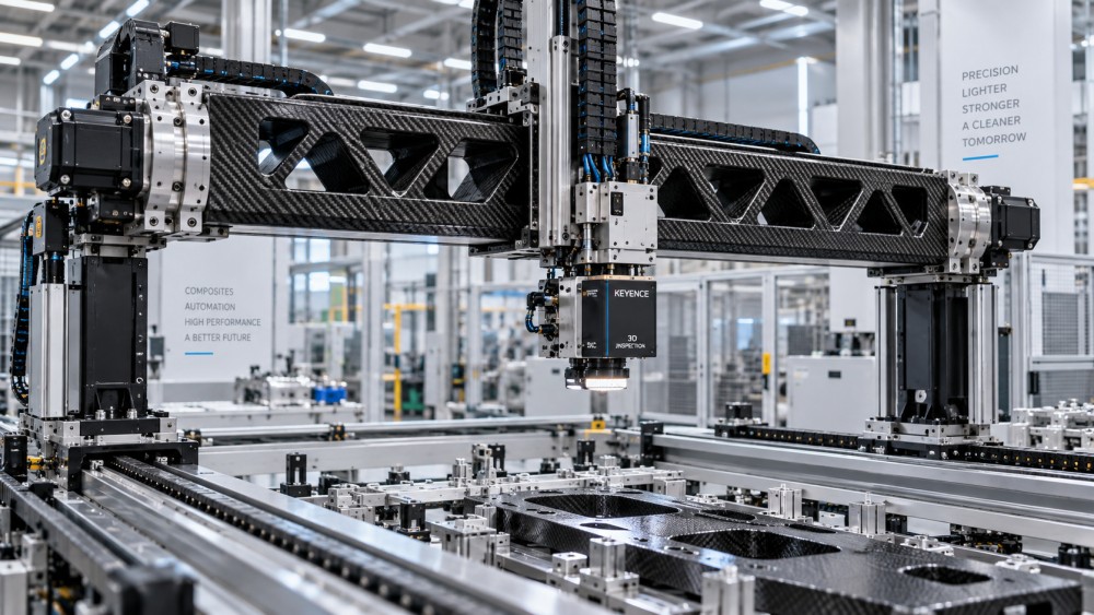
Linear-motion and inspection equipment. Moving crossbeams, camera supports, sensor frames, and cable-management structures can benefit when rapid acceleration makes deflection and vibration visible in the process result. A composite beam can be designed with directional reinforcement to resist the bending and torsion that affect sensor position. The assembly must still account for rail alignment, mounting flatness, thermal expansion, and repeatable fastening. A stiff beam with poorly controlled interface geometry will not produce a precise axis.
Fluid-handling and chemical-exposed structures. Fiber-reinforced parts can be useful where corrosion resistance and low weight are both relevant, such as supports, covers, instrument structures, and non-pressure structural modules near aggressive media. This is not a blanket recommendation for wetted or pressure-containing parts. Resin selection, chemical exposure, temperature, permeation, and relevant pressure-equipment requirements must be assessed separately. A structural laminate suitable for a dry enclosure may be unsuitable for a chemically exposed pressure boundary.
Portable industrial equipment and field-deployed systems. Transport frames, inspection devices, mobile tooling, and service equipment often carry a mass penalty throughout their lifecycle. Lower weight may simplify manual handling and reduce transport constraints. Yet field use also increases the importance of impact resistance, repairability, UV exposure, moisture cycling, and visible damage detection. A high-modulus laminate optimized for stiffness can be less forgiving of impact than a more robust glass- or hybrid-fiber construction.
The hidden constraints are usually at the joints
Composite structures are efficient when loads are spread through the laminate. Conventional mechanical assemblies often apply loads through bolts, threads, clamps, pins, bearing seats, and small contact areas. This mismatch causes many late-stage problems.
Drilling a hole through a laminate interrupts fibers and can introduce stress concentrations. High bolt preload can crush the material through its thickness. Repeated clamp loads can cause local relaxation. A bonded metal insert can create thermal-expansion mismatch, while a machined metal end fitting can transfer a sharp load into the composite tube wall. None of these issues makes composites impractical; they mean interface design must begin early.
Common approaches include co-cured or bonded inserts, metallic end fittings, local laminate reinforcement, load-spreading washers or flanges, adhesive-plus-fastener joints, and molded geometry that distributes force over a larger area. Each method has implications for inspection, repair, assembly sequence, and tolerance control. If a part must be repeatedly disassembled in service, a removable joint with replaceable hardware may be preferable to a structurally elegant but inaccessible bonded joint.
The same principle applies to precision features. Composite molding can produce stable near-net geometry, but it is not a substitute for every machined datum. Critical bearing bores, sealing faces, rail pads, and alignment surfaces may require bonded or co-molded metallic features, followed by controlled machining. The project specification should distinguish between cosmetic dimensions, molded structural dimensions, and true functional datums. Applying metal-machining tolerances indiscriminately to a large molded laminate can increase cost and scrap risk without improving assembly performance.
Thermal, environmental, and electrical behavior need early decisions
Fiber composites can behave very differently from metal assemblies under changing temperature. Carbon fiber has a low coefficient of thermal expansion along the fiber direction, while the polymer matrix and transverse laminate directions behave differently. This can be valuable in dimensional-control applications, but only when the layup and attached materials are considered together. A carbon-composite beam bonded to aluminum end blocks may experience internal stress as temperature changes because the materials expand at different rates.
Moisture uptake, ultraviolet exposure, cleaning chemicals, operating temperature, and fire-performance requirements are equally important. Resin chemistry is not a detail to be chosen after geometry is frozen. Epoxy, vinyl ester, phenolic, thermoplastic, and other systems offer different combinations of processability, temperature capability, chemical resistance, flame behavior, and toughness. The correct choice follows the service environment and manufacturing route.
Carbon fiber also introduces electrical considerations. It is conductive enough to require attention around electrical isolation, grounding paths, electromagnetic behavior, and galvanic contact with aluminum in the presence of moisture. Isolation layers, suitable coatings, and joint design can manage galvanic risk, but ignoring the issue can lead to corrosion at metal-composite interfaces rather than in the composite itself.
Cost should be evaluated at assembly level
A comparison based only on part price usually favors the incumbent metal component, especially where the metal design is already mature and produced at volume. Composite tooling, engineering development, process qualification, and inspection planning can create meaningful upfront cost. Low-volume projects may therefore struggle to justify a custom composite part unless the performance gain solves a costly system limitation.
The more useful comparison includes the surrounding consequences: smaller drives, lower energy demand during frequent motion, reduced counterweight, easier installation, lower corrosion protection needs, fewer fabricated subcomponents, or a redesigned assembly with less hardware. These savings are not guaranteed and should not be assumed. They need to be traced to actual changes in the bill of materials, cycle-time requirement, installation method, or maintenance plan.
Conversely, lifecycle cost can rise if the design requires specialist repair, if damage inspection is difficult, or if an imported component creates long lead times for a critical spare. A project plan should define what happens after impact damage, overload, or field modification. Unlike a bent steel bracket that may be visibly deformed, internal delamination in a composite can require non-destructive inspection or a predefined replacement rule.
Manufacturing route determines repeatability
“Composite manufacturing” covers processes with very different tolerance capability, fiber-volume consistency, surface finish, tooling cost, and production cadence. Prepreg layup with autoclave curing, out-of-autoclave prepreg, resin transfer molding, compression molding, filament winding, pultrusion, and automated fiber placement are not interchangeable choices.
A straight, repeatable tubular member may suit filament winding or pultrusion. A complex shell with integrated ribs and local reinforcement may suit molded processes. A highly loaded aerospace-style structure may require a more controlled layup and cure route than a general industrial cover. The selected process must align with the quantity, geometry, quality-critical characteristics, and inspection access of the part.
For project execution, the critical deliverable is a shared definition of what must be controlled. That includes fiber orientation where it affects load capacity, resin system, cure cycle or process window, dimensional datums, permitted void or porosity criteria where relevant, insert placement, bond-line requirements, and inspection method. A drawing that only specifies external dimensions and material name is usually insufficient for a load-bearing composite component.
Supplier evaluation should focus on control of the full process
A supplier’s ability to mold a visually acceptable part is not the same as its ability to deliver a structurally repeatable precision component. The review should examine whether the supplier can translate functional requirements into laminate design, tooling, joining strategy, and inspection records.
Useful evidence includes process documentation, traceability for reinforcement and resin materials, defined handling and storage controls for moisture- or temperature-sensitive materials, calibration of measurement equipment, and a clear method for managing design changes. For bonded assemblies, bond-surface preparation and adhesive cure control are often as important as the laminate itself. For parts with critical interfaces, ask how datums are established and verified after cure, trimming, machining, and insert installation.
Qualification should reflect the actual failure risks. Coupon testing can confirm basic laminate properties, but coupons do not fully represent a joint, an insert, a curved transition, or a complex load introduction zone. Component-level tests, proof loads, fatigue evaluation where cyclic loading is significant, and dimensional checks under realistic fixture conditions provide more meaningful evidence. The exact test program should be proportionate to the consequence of failure and the uncertainty in the design.
Start with the limiting requirement
Precision composite parts reduce weight without sacrificing structural stiffness when they are applied to a defined system bottleneck: excessive moving inertia, deflection at a sensitive tool point, vibration in a long-span member, corrosion-driven mass and maintenance burden, or installation limits imposed by handling capacity. They are less effective when the project treats composite as a drop-in material substitution and leaves geometry, joints, tolerances, and validation unchanged.
The strongest specifications state the performance that must be preserved or improved—deflection, torsional rotation, natural frequency, positional stability, load capacity, or allowable mass—then allow the material architecture and manufacturing method to serve those requirements. That approach keeps the decision anchored in assembly performance, where lightweight design either proves its value or fails to do so.
Related News
- How to vet North American fluid dynamics engineering firms for CFDOct 13, 2026Searching for fluid dynamics engineering North America? Discover how to vet CFD firms, assess validation, and choose a partner for confident design decisions.
- Does higher hardness improve heavy equipment abrasion resistance?Oct 14, 2026Does higher hardness improve heavy equipment abrasion resistance? Discover how wear mechanisms, toughness, and testing guide material choices to extend component life and reduce downtime.
- How to choose high-impact wear materials for mill linersOct 13, 2026Choose high-impact wear materials for mills with confidence. Compare liner toughness, wear resistance, and cost per tonne to improve reliability. Explore our practical selection guide.
- When do tighter tolerances justify precision manufacturing solutions for aluminum parts?Oct 10, 2026Precision manufacturing solutions for aluminum parts: learn when tighter tolerances improve fit, sealing, alignment, reliability, and production value.
Related News
- 00
0000-00
How to choose engineering plastics for gears without lubrication - 00
0000-00
How to vet North American fluid dynamics engineering firms for CFD - 00
0000-00
How to qualify a semiconductor equipment parts supplier for traceability - 00
0000-00
How heat treatment affects wear-resistant special steel valve parts - 00
0000-00
Does higher hardness improve heavy equipment abrasion resistance?
Dr. Alistair Vaughn
Strategic Intelligence Center