








Yes—a machining supplier can hold tight tolerances on large shafts, but proving that capability takes more than a machine specification. For technical evaluators selecting a heavy engineering components machining supplier, the decisive questions concern shaft deflection, thermal stability, workholding, material condition, and measurement uncertainty. A shaft may meet its diameter tolerance yet fail requirements for straightness, roundness, or bearing-seat alignment.
The purchasing risk is rarely an obvious lack of equipment. More often, it is a gap between what a supplier can produce under favorable conditions and what it can consistently deliver on your material, geometry, and production schedule. The evaluation should therefore connect drawing requirements to a credible process route—and that process route to inspection evidence.
“Tight tolerance” is not one requirement
Before comparing suppliers, separate the shaft’s acceptance criteria. A bearing seat, coupling interface, seal journal, and long unsupported span perform different jobs. Their tolerances should reflect those functions rather than a general demand for precision everywhere.
These characteristics are related, but they are not interchangeable. A micrometer reading does not establish cylindricity. A low runout reading near one support does not prove that distant bearing seats share the required alignment. Even a smooth-looking journal can have waviness that matters in a demanding bearing or sealing application.
Start with an agreed drawing interpretation. Confirm the applicable GD&T standard, datum features, inspection conditions, and acceptance rules. Where a requirement is ambiguous, resolve it before quotation—not after the shaft reaches final inspection.
The shaft moves even when the machine does not
Large-shaft machining is partly a problem of controlling movement. Cutting forces, gravity, support reactions, and temperature all influence the relationship between the tool and the workpiece. Machine positioning accuracy is only one contributor.
Deflection and support placement
A long shaft behaves as a flexible structure. Its sensitivity depends on length, diameter, section changes, material stiffness, and how it is supported. Hollow sections and slender regions may respond very differently from the heavy journals beside them.
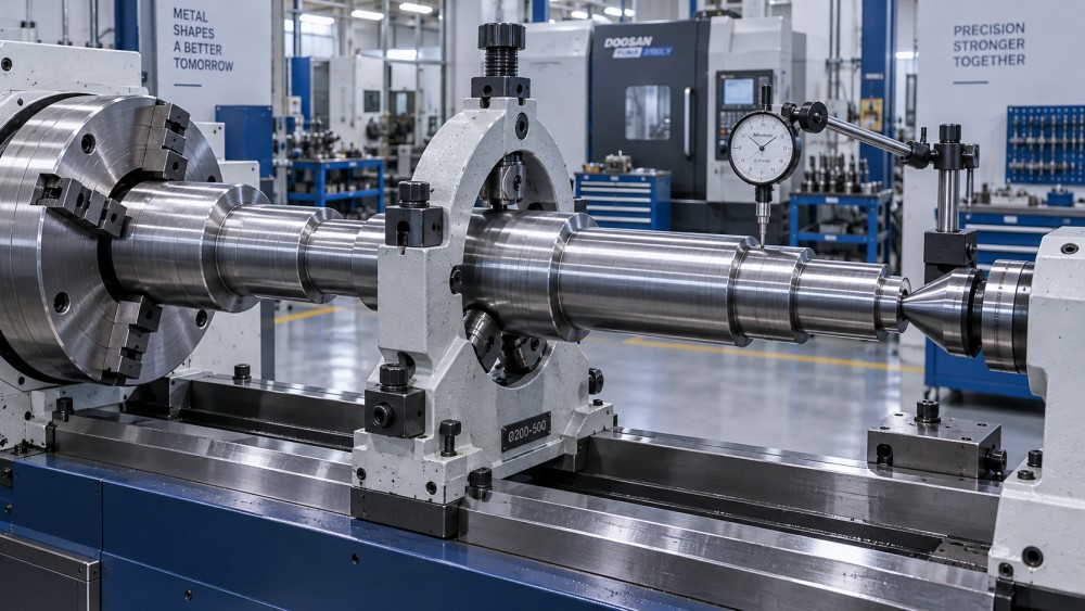
Ask the supplier to explain the planned use of centers, steady rests, follow rests, or other supports. The important question is not simply whether these accessories exist, but where they will act and how their forces will be controlled. Excessive support pressure can distort the workpiece; insufficient support can allow chatter, taper, or local form error.
A credible plan also addresses support transitions. If a steady rest must move during machining, what prevents the new setup from introducing a different axis? If its contact surfaces are unfinished, how will their irregularity affect the cut?
Temperature and dimensional drift
Large shafts have substantial thermal mass, and their temperature may remain uneven after machining, washing, or movement between areas. A temperature-controlled inspection room does not automatically mean the workpiece has reached thermal equilibrium.
For perspective, using a typical steel expansion coefficient of approximately 11–12 micrometers per meter per degree Celsius, a 300 mm diameter changes by roughly 3.3–3.6 micrometers for a 1°C temperature change. Over a 3 m length, the corresponding change is approximately 33–36 micrometers. These are illustrative estimates; actual behavior depends on the alloy and temperature distribution.
For micrometer-level requirements, thermal conditions are therefore part of the acceptance process. Ask how workpiece temperature is measured, what stabilization criteria are used, and how dimensional results relate to the drawing’s reference temperature, commonly 20°C. Compensation may help, but it cannot reliably erase an unknown temperature gradient.
Material condition can undo a good finishing operation
A shaft that looks stable during machining may move after substantial stock removal. Forging, rolling, heat treatment, straightening, and earlier machining can leave residual stresses that redistribute as material is removed.
This is why the process route deserves as much attention as the final machine. Depending on the alloy and application, an appropriate route may include rough machining, a qualified stress-relief operation, semi-finishing, and final finishing. Stress relief is not automatically suitable for every material or heat-treatment condition; it must remain compatible with required mechanical properties.
Review the supplier’s plan for:
- Incoming material verification: traceability, heat-treatment condition, and any specified hardness or internal-quality checks.
- Stock removal: allowances and sequencing intended to limit uneven stress redistribution.
- Intermediate checks: opportunities to detect movement before the final finishing allowance is consumed.
- Post-machining operations: treatment, coating, keyway cutting, or other steps that could alter geometry.
A supplier should not promise that one last grinding pass will solve every distortion problem. Grinding can correct geometry within available stock, but it cannot guarantee long-term stability in a poorly controlled material condition.
Evaluating a heavy engineering components machining supplier beyond its equipment list
A large CNC lathe establishes capacity, not demonstrated capability. Travel, swing, and nominal positioning accuracy do not establish whether the complete system can produce your shaft within tolerance.
Ask for a proposed operation sequence that identifies datum creation, workholding changes, support locations, finishing methods, and inspection stages. The explanation should be specific enough to show where error could enter and how the supplier intends to control it.
For bearing seats, the supplier may propose finish turning, cylindrical grinding, or another qualified process. None is universally best. Suitability depends on material hardness, diameter, length, accessibility, surface requirements, and form tolerances. Grinding also introduces its own controls, including wheel condition, heat input, and protection against surface damage.
Pay particular attention to features machined in separate setups. When two distant journals must meet a common alignment requirement, the supplier needs a convincing method for preserving or re-establishing the reference axis. “We machine both to size” is not an adequate answer.
Relevant experience helps, but similarity matters more than impressive photographs. Request evidence from components with comparable slenderness, material condition, feature spacing, and tolerances. A short, stiff rotor does not demonstrate capability for a long, flexible shaft simply because both are heavy.
Inspection evidence should survive a technical challenge
The strongest inspection report is not necessarily the one with the most numbers. It is the one whose measurement strategy matches the drawing and whose results can be interpreted with confidence.
Check the method, not just the instrument
External micrometers can verify selected diameters, but sparse readings can miss lobing or local variation. Indicator measurements can assess specified runout in a suitable setup, but the readings depend on datum establishment and rotational support. A large CMM may be useful, yet its name alone says nothing about the uncertainty achieved on a particular shaft.
Portable measurement systems can be valuable for large assemblies and spatial relationships. They are not automatically suitable for micrometer-level journal form verification. Each characteristic needs a method with adequate resolution, uncertainty, and sampling coverage.
Account for sag and fixture influence
For a long shaft, support conditions can change the measured result. Request the inspection orientation, support locations, and rationale. Where gravitational sag is significant, the agreed method may require defined supports, validated compensation, or another engineering approach consistent with the specification.
The fixture must not force the shaft into an apparently acceptable shape. Likewise, differences between machining supports and inspection supports should be understood rather than treated as unexplained measurement noise.
Agree how uncertainty affects acceptance
Calibration is necessary, but it does not capture every source of uncertainty in the measurement process. Temperature, alignment, fixture repeatability, probing strategy, surface condition, and operator technique can all contribute.
Ask for the estimated measurement uncertainty on the critical characteristics and the decision rule used near tolerance limits. Guard bands may be appropriate where the consequences of accepting a nonconforming shaft are serious, but the rule should be agreed commercially and technically before production.
Turn the quotation into a capability test
Rather than asking, “Can you hold this tolerance?”, ask the supplier to show how it will establish and verify each critical requirement. A useful pre-award review can be built around five requests:
- A marked-up drawing: identify difficult features, unclear requirements, and proposed inspection methods.
- A process route: show material preparation, datum strategy, support arrangements, and finishing operations.
- Relevant evidence: provide anonymized reports or records from genuinely comparable work where available.
- An inspection plan: define measurement coverage, temperature conditions, uncertainty, and acceptance rules.
- A deviation procedure: explain how unexpected distortion or insufficient finishing stock will be reported before unauthorized rework.
For repeat production, ask how consistency will be monitored. Capability indices can help when the process is stable and enough representative data exist. A single successful first article is useful evidence, but it does not establish statistical capability. For one-off shafts, staged inspections and documented setup controls are often more informative than a capability number based on inadequate data.
Watch for answers that replace engineering detail with reassurance: “our machine is accurate enough,” “we always achieve that finish,” or “inspection will confirm it.” More credible responses acknowledge the difficult features, identify controls, and explain the limits of available evidence.
The decision is about controlled risk
The right supplier is not necessarily the one claiming the tightest achievable number. It is the one whose process, metrology, and material controls fit the shaft’s functional requirements—and whose evidence makes remaining risk visible.
That approach reflects GPCM’s focus on connecting component-level precision with power-transmission performance. Bearing fits, journal alignment, and surface condition influence friction, wear, and service reliability; they should be evaluated together rather than reduced to a diameter on an inspection sheet.
So, can a machining supplier hold tight tolerances on large shafts? Yes, when the tolerance is clearly defined, the workpiece’s behavior is controlled, and the measurement method can demonstrate conformity. Before awarding the job, require a traceable path from drawing to process to inspection. That is the difference between buying a reassuring claim and making a defensible technical decision.
Related News
- Can a machining supplier hold tight tolerances on large shafts?Oct 17, 2026Choosing a heavy engineering components machining supplier? Discover how to verify tight tolerances on large shafts, assess inspection evidence, and reduce sourcing risk.
- How to Assess Power Transmission Quality Before Failures Reach the Production LineOct 13, 2026Power transmission quality assessment made practical: detect vibration, heat, lubrication, alignment, and backlash issues before they disrupt production.
- Buying Power Transmission Component Castings: Which Inspection Records Matter Most?Oct 12, 2026Power transmission component castings demand traceable inspection records. Learn which material, dimensional, NDT, and repair documents protect quality and reliability.
- Power Transmission Component Casting Defects That Shorten Gearbox Service LifeOct 11, 2026Power transmission component casting defects can trigger gearbox leaks, vibration, and bearing failure. Discover inspection priorities and repair-or-replace guidance.
Related News
- 00
0000-00
When do precision ground gears reduce noise in high-speed gearboxes? - 00
0000-00
How pressure ratings affect the price of flow control components - 00
0000-00
How to choose gear materials for high-load industrial gearboxes - 00
0000-00
How to choose engineering plastics for gears without lubrication - 00
0000-00
How to vet North American fluid dynamics engineering firms for CFD
Power Trans Designer
Strategic Intelligence Center