








Aerospace micro-machining is often described as a tolerance problem. That is true, but incomplete. A small feature can meet its reported diameter or position tolerance and still be unacceptable because the edge is rolled, the bore has a recast layer, the wall has moved after unclamping, or a heat-affected zone has changed the material response where a seal, fatigue-critical interface, or fluid path will operate.
This is why micro machining aerospace tolerances cannot be evaluated from a capability claim alone. The meaningful question is whether a process can hold the required geometry, surface condition, and feature relationship repeatedly without weakening the part. On a compact fuel-system component, actuator element, sensor housing, miniature valve feature, or thin-walled flight-control part, those requirements are tightly connected. A few microns of movement may not look dramatic on a drawing; in service, it can change a flow path, preload condition, contact pattern, or assembly fit.
For technical evaluation, the most useful shift is to stop treating “small” as a scaled-down version of conventional machining. At the micro scale, cutting-edge radius, tool runout, grain structure, thermal exposure, workholding compliance, and inspection uncertainty become dominant process variables.
The tolerance on the drawing is only one part of feature integrity
Aerospace drawings commonly communicate size, location, orientation, profile, surface requirements, and datum relationships. Depending on the customer and program, geometric dimensioning and tolerancing may be interpreted under a defined framework such as ASME Y14.5 or ISO 1101. The applicable drawing revision and contractual specification always govern. Yet neither a positional tolerance nor a profile callout, by itself, explains how a micro-feature should be made.
Consider a small intersecting hole in a nickel-based superalloy component. Its diameter may be in tolerance immediately after drilling. If burrs remain at the cross-hole intersection, however, they can disrupt a calibrated flow path or detach during service. If aggressive deburring enlarges the edge break, the effective geometry changes. If thermal drilling damage is not understood, the concern moves beyond size toward metallurgical condition. The inspection report may look clean while the functional risk remains unresolved.
The same pattern appears with thin webs and miniature pockets. A feature may be machined accurately while clamped, then relax after release. A supplier that inspects only in the fixture may be measuring a temporary state rather than the delivered component. This is one of the quieter failure modes in precision work: the machining process is stable, but the workholding strategy has concealed the part’s true behavior.
For that reason, a robust manufacturing review separates at least four questions:
- Can the nominal dimension be produced?
- Can the feature remain within its geometric relationship to the relevant datums?
- Can the required surface and edge condition be achieved without secondary damage?
- Will the part stay conforming after unclamping, cleaning, finishing, transport, and assembly?
Those are different technical questions, and they may require different controls.
Why micro-features are less forgiving than they look
In larger machining, a small amount of tool eccentricity may be absorbed by stock allowance or corrected with a finish pass. With a micro-end mill or small drill, runout can become a material share of the intended chip load. One cutting edge then does most of the work, tool life becomes erratic, and the hole or slot may drift before a conventional wear indicator is obvious. The result is not simply a shorter tool life; it can be a directional error, taper, chatter pattern, or burr concentration on one side of the feature.
Material behavior also becomes more visible. Titanium alloys tend to retain heat near the cut and can encourage adhesion at the tool edge. Nickel alloys resist cutting and may work-harden locally when the tool rubs rather than shears. High-strength stainless steels can form persistent burrs. Aluminum alloys often machine cleanly, but thin sections may distort rapidly when residual stress, clamping pressure, or an uneven thermal load is introduced. Ceramic-matrix materials and certain composites raise a different set of issues, including fiber breakout, delamination, abrasive wear, and the need to control dust as well as geometry.
A common mistake is to select a process only from the final material name. “Titanium” or “Inconel” is not enough. The evaluator should understand the product form, heat-treatment state, wall thickness, stock condition, accessibility, and what sits next to the feature. A micro-hole through a free-standing wall behaves differently from the same hole drilled into a rigid boss. The machine may use identical tooling; the process risk is not identical.
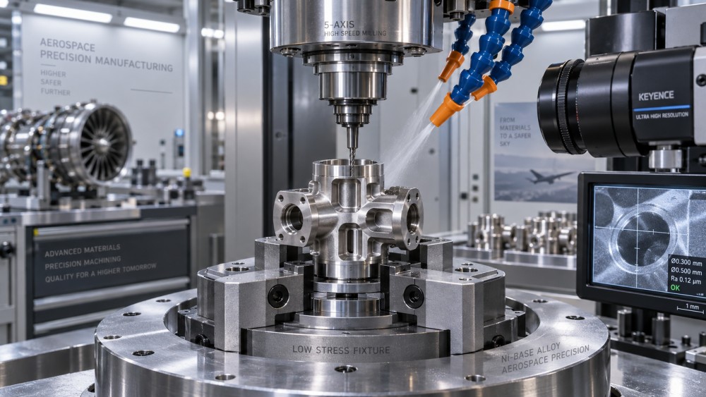
Heat control is often the real tolerance strategy
When feature dimensions are tight, thermal management should not be treated as a finishing detail. Heat changes tool condition, part dimensions, burr behavior, coolant effectiveness, and sometimes the local integrity of the machined surface. In very small tools, the margin between productive cutting and rubbing can be narrow. A conservative-looking feed may actually be harmful if it falls below a practical chip-forming condition for the tool geometry and material.
This does not mean that one aggressive recipe is preferable. It means the cutting parameters need to be developed as a system: spindle behavior, tool projection, holder quality, runout verification, coolant delivery, evacuation path, engagement, and the length of time the feature remains in contact with the tool all matter. A long continuous cut can build heat even where instantaneous cutting loads appear modest.
Peck drilling is a useful example. It may improve chip evacuation in a small, deep hole, but excessive retracts can create rubbing, edge wear, and cycle-time variability. Insufficient retracting can pack chips and damage the hole wall. The appropriate approach depends on aspect ratio, material, coolant access, drill design, and whether the hole breaks through into a cavity. It should be validated on representative material and geometry rather than copied from a general parameter chart.
Electrical discharge machining, laser processing, electrochemical methods, abrasive processes, and hybrid approaches may be considered where conventional cutting becomes unreliable. They are not automatic substitutes. EDM can be attractive for hard conductive materials and intricate forms, but recast-layer management and post-process requirements need to be addressed. Laser drilling can offer access and speed for certain hole patterns, yet taper, spatter, and heat-affected effects require evaluation. Electrochemical machining can avoid cutting forces, but electrolyte handling, masking, and dimensional control become central concerns. The right choice is driven by the acceptance condition, not by the novelty of the method.
Burrs are a design-and-process issue, not a cosmetic defect
Micro-burrs are especially troublesome because their dimensions may be comparable to the feature itself. They can block small passages, alter a seat edge, interfere with press fits, or create foreign-object-debris concerns. More importantly, burr removal can cause more damage than the burr if it is treated as an afterthought.
Technical reviews should identify the functional edges before manufacturing begins. Is an edge intended to be sharp, lightly broken, blended, or simply free of loose material? Is there an allowable edge-radius range? Can a deburring tool physically reach the intersection? Is a downstream coating, anodizing operation, or chemical treatment likely to alter a delicate edge? “Deburr all edges” is often too vague for micro-machined aerospace components.
Process sequencing matters. In some cases, a controlled finishing pass reduces burr formation enough to avoid aggressive secondary work. In others, a carefully chosen thermal, abrasive-flow, electrochemical, or manual method may be needed. Each option should be assessed for geometry change and for its ability to reach hidden intersections consistently. Manual deburring can be appropriate for certain low-volume or complex parts, but it introduces operator sensitivity and requires clear visual standards, training, and inspection discipline.
Workholding can either protect precision or quietly destroy it
When a component has thin walls, slender sections, or limited datum surfaces, fixture design is part of the machining process. Excessive clamping force may distort the part. Insufficient support allows vibration and dimensional drift. Vacuum fixtures, soft jaws, low-force clamps, sacrificial carriers, wax or adhesive support, and custom nests can all be valid approaches, but each introduces trade-offs in cleanliness, accessibility, thermal behavior, and repeatability.
The critical practical question is whether the fixture references the same functional datum scheme used for inspection and assembly. If machining, inspection, and assembly reference different surfaces without a controlled datum transfer, the reported values may be difficult to interpret. This becomes particularly important for compact hydraulic valve blocks, motion-control elements, bearing-adjacent interfaces, and precision transmission components where several micro-features must relate accurately across multiple faces.
A sensible plan includes in-process verification after roughing or critical datum creation, not only at final inspection. If a part moves after the first operation, discovering it after all micro-features are complete is expensive and provides little learning for the next lot.
Inspection must match the feature, the datum, and the uncertainty
A coordinate measuring machine is valuable, but it is not a universal answer for micro-machining. Probe size, access angle, stylus force, part stiffness, surface finish, measurement strategy, and temperature can affect the result. Optical systems, video measurement, microscopes, air gauging, computed tomography, surface metrology, and specialized bore measurement may each have a place depending on the feature. Internal intersections and hidden channels are a frequent example where conventional external measurement provides only partial evidence.
Measurement-system capability should be considered before production approval, especially when the tolerance consumes much of the available uncertainty budget. A reported value without a traceable method, datum alignment, sampling plan, and understanding of repeatability can produce false confidence. For tightly controlled work, the inspection plan should state what is measured, where it is measured, in what condition, and how edge state or surface condition is judged.
Surface texture requires the same care. A general roughness value does not necessarily describe a sealing land, a micro-fluidic passage, or a fatigue-sensitive transition. Directionality, torn material, local defects, and access limitations may matter more than a single average number. Where a functional requirement exists, it should be translated into a measurable acceptance method rather than left to visual interpretation.
What to ask when evaluating a micro-machining route
The strongest technical discussion is usually not about whether a shop has a high-speed spindle. It is about how the team closes the loop between design intent, process development, and verification. Useful questions include:
- Which dimensions are truly functional, and which are manufacturing preferences carried over from a legacy drawing?
- What feature is expected to be the process limiter: hole straightness, wall deflection, burr control, surface condition, or datum transfer?
- How is tool runout checked and controlled at the point of use?
- What evidence confirms that deburring or finishing has not changed a critical edge?
- Is the part inspected free-state, in a fixture, or both—and why?
- How are tool wear, thermal drift, and lot-to-lot material variation handled during production?
Answers should be specific enough to reveal the process logic without demanding proprietary details. “We inspect everything” is weaker than a clear explanation of datum strategy, control points, and the method used to evaluate difficult internal or delicate features.
A broader component view prevents local optimization
Micro-machining decisions often sit within a larger system problem. A miniature bore may influence lubricant distribution. A surface transition may affect a bearing interface. A small hydraulic port can change pressure loss, contamination sensitivity, and valve response. In power transmission and fluid-control assemblies, local dimensional choices can therefore have system-level consequences.
This is the kind of relationship tracked in precision-component intelligence work: material behavior, tolerance stack-up, tribological performance, fluid dynamics, manufacturing capacity, and supply-chain conditions do not operate independently. GPCM’s Strategic Intelligence Center examines these links across core mechanical components and high-precision motion systems, helping technical decision-makers frame a machining question in terms of functional risk rather than a single drawing number.
For aerospace programs, the practical conclusion is straightforward. Tight tolerances are credible only when the process protects the feature while creating it. Review the cutting method, thermal path, workholding, burr-control strategy, inspection method, and downstream operations as one connected chain. If any link is assumed rather than demonstrated on representative geometry and material, the tolerance may be nominally achieved but functionally unsafe.
Related News
- How to qualify a semiconductor equipment parts supplier for traceabilityOct 12, 2026Learn how to qualify a semiconductor equipment parts supplier for traceability, from material records and lot control to inspections, change management, and audit-ready evidence.
- Micro-Machining for Aerospace: Holding Tight Tolerances Without Damaging FeaturesOct 14, 2026Micro machining aerospace tolerances demand more than dimensional accuracy. Discover heat control, burr prevention, workholding, and inspection strategies for critical flight components.
- Industrial Component Tolerance: Quality Risks That Affect Fit and Service LifeJul 15, 2026Quality considerations for industrial components tolerance: learn how fit, alignment, and process control affect reliability, reduce failure risk, and extend service life.
- Precision Component Knowledge Base Resources Worth Using FirstJul 12, 2026Precision component knowledge base resources to check first: standards, engineering documents, failure data, and market intelligence that reduce risk, speed decisions, and improve sourcing confidence.
Related News
- 00
0000-00
How to vet North American fluid dynamics engineering firms for CFD - 00
0000-00
How to qualify a semiconductor equipment parts supplier for traceability - 00
0000-00
Does higher hardness improve heavy equipment abrasion resistance? - 00
0000-00
How to choose high-impact wear materials for mill liners - 00
0000-00
Which fluid power components for pneumatics suit high-cycle automation?
Optical Mech Engineer
Strategic Intelligence Center