








How Can You Prevent Hydraulic Pump Cavitation After Installation?
How do I prevent hydraulic pump cavitation after installation? This critical question affects pump reliability, energy efficiency, and the service life of an entire fluid power system.
From suction-line design and reservoir conditions to oil viscosity and air leaks, small installation errors can trigger damaging cavitation after an otherwise successful commissioning process.
This guide explains the practical checks, engineering priorities, and operating controls needed to protect hydraulic pumps, reduce avoidable downtime, and establish stable long-term system performance.
Start by Confirming Whether the Problem Is Cavitation
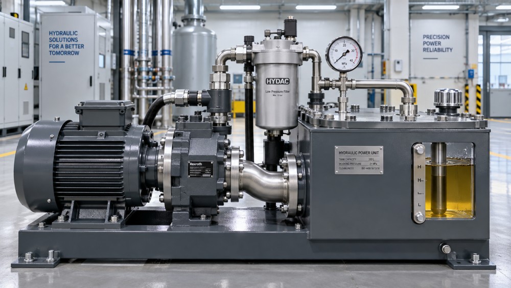
Before changing components, confirm that the pump is actually cavitating. Cavitation is often confused with aeration, mechanical wear, pressure instability, or valve-related noise.
Typical cavitation symptoms include a harsh rattling or gravel-like sound, fluctuating outlet pressure, elevated vibration, reduced actuator speed, foamy oil, and falling pump efficiency.
True cavitation occurs when inlet pressure drops below the fluid vapor pressure, allowing vapor cavities to form within the pump inlet or rotating group.
When those vapor cavities move into higher-pressure zones, they collapse violently. The repeated implosions can erode metal surfaces, damage bearings, and shorten pump life.
Aeration creates similar operational symptoms but has a different source. It occurs when outside air enters the hydraulic fluid through leaks, poor reservoir design, or turbulent return flow.
Both conditions deserve immediate attention because each reduces lubrication quality, raises noise levels, increases oxidation, and makes hydraulic control less predictable during normal production.
Inspect removed filters, pump case-drain flow, oil appearance, and noise patterns before deciding on corrective action. Replacing a pump without correcting inlet conditions usually repeats the failure.
Check the Suction Line Before Adjusting Anything Else
The suction line is the most important inspection point after installation. Most hydraulic pump cavitation problems begin because the inlet path restricts fluid flow.
A pump cannot create fluid supply. It can only create a pressure difference that encourages reservoir oil to flow toward the inlet port.
If the suction hose is undersized, excessively long, sharply bent, internally damaged, or poorly routed, inlet losses increase and available pressure decreases rapidly.
Use the pump manufacturer’s recommended inlet diameter as the minimum requirement. In many applications, a larger suction line provides a useful operating margin.
Keep the inlet run as short and direct as practical. Every elbow, reducer, restrictive fitting, hose collapse, and unnecessary elevation change raises suction resistance.
Avoid fittings that reduce the effective bore diameter below the pump inlet size. Nominal hose size alone does not guarantee adequate internal flow area.
Flexible hoses require special attention because some types can soften, delaminate, or collapse under vacuum conditions even when their exterior appears undamaged.
Inspect the hose liner, bend radius, clamp position, and routing near hot surfaces. A line that looks acceptable at rest may restrict flow after temperature rises.
Where possible, measure vacuum at the pump inlet during normal operation. Comparing the reading with pump specifications gives a clearer answer than relying only on noise.
Eliminate Air Leaks on the Inlet Side
An inlet-side air leak may not create visible oil leakage because the suction line operates below atmospheric pressure while the pump is running.
Instead of leaking oil outward, a defective connection can draw air inward. This makes suction-side faults harder to detect during ordinary visual inspections.
Examine hose clamps, threaded adapters, O-rings, flange seals, welded connections, pickup tubes, and pump inlet fittings for imperfect sealing or mechanical damage.
Pay particular attention to connections that were disturbed during installation. Misaligned fittings, overtightened clamps, damaged O-rings, and incompatible seal materials are common causes.
Use proper seals designed for hydraulic oil and the expected temperature range. Temporary thread treatments or unsuitable gasket compounds can break down and contaminate the system.
A vacuum test can help identify inlet leaks before the machine returns to full production. Stable vacuum retention suggests that the suction circuit is properly sealed.
Oil foaming in the reservoir is a valuable warning sign, especially when it increases after pump startup. Persistent foam often indicates entrained air or return-line turbulence.
Correcting air ingress protects more than the pump. Entrained air can also cause erratic cylinders, spongy motion, unstable proportional valves, and inaccurate pressure control.
Verify Reservoir Level, Venting, and Internal Flow Conditions
A properly sized reservoir supports pump operation by storing sufficient fluid, releasing entrained air, dissipating heat, and separating return flow from the suction pickup.
Low oil level is one of the simplest and most overlooked causes of post-installation cavitation. It can expose the pickup tube or create a vortex above it.
Check fluid level with the equipment in its normal operating condition. Extended cylinders, accumulators, and remote circuits can significantly change reservoir volume requirements.
The suction pickup should remain adequately submerged during all operating modes, including cold startup, rapid actuator movement, and periods of peak system demand.
Reservoir breathers also matter. A blocked, undersized, or contaminated breather can create vacuum inside the tank as oil leaves, restricting flow to the pump.
Inspect the breather element and confirm that its airflow capacity matches expected reservoir volume changes. Do not assume a clean-looking breather has acceptable flow performance.
Return lines should discharge below the oil surface and away from the suction pickup. Returning oil directly near the inlet can entrain air and disturb fluid supply.
Internal baffles should promote calm circulation rather than isolate useful oil volume. Poor baffle placement can trap air, create excessive turbulence, or restrict deaeration time.
Use Hydraulic Oil With the Correct Viscosity at Operating Temperature
Fluid viscosity has a direct effect on inlet performance. Oil that is too viscous creates excessive friction losses in suction lines, filters, fittings, and pump inlet passages.
Cold startup is particularly demanding because hydraulic oil can be substantially thicker than it is at normal operating temperature. Cavitation may appear only during the first minutes.
Review the pump manufacturer’s recommended viscosity range for startup, normal operation, and maximum temperature. These limits are more useful than selecting oil by ISO grade alone.
An oil grade that performs well in a warm factory may cause inlet starvation in an unheated outdoor installation. Climate and duty cycle matter.
Conversely, oil that becomes too thin at high temperature may reduce lubrication film strength, increase internal leakage, and accelerate component wear despite good inlet flow.
Measure actual oil temperature near the reservoir and, when possible, at the pump inlet. Surface temperature readings alone may not represent fluid conditions accurately.
Use tank heaters, controlled warmup sequences, or lower-temperature fluid formulations when cold-weather operation is unavoidable. Avoid immediately applying full load to a cold hydraulic system.
Do not mix oils casually to alter viscosity. Incompatible additive packages can reduce oxidation stability, damage seals, compromise filtration, and create expensive maintenance problems.
Review Suction Strainers and Inlet Filtration Strategy
Suction strainers are often installed with good intentions, but an improperly selected element can become a major source of inlet restriction and pump cavitation.
Fine filtration belongs primarily on return, pressure, or offline kidney-loop circuits, where pressure differential can be monitored without starving the pump inlet.
If a suction strainer is necessary, select one with very low pressure loss at maximum flow, expected viscosity, and anticipated contamination loading.
Remember that a clean strainer can still be restrictive when oil is cold. Its pressure drop must be evaluated under the most demanding operating condition.
Inspect whether the strainer mesh is damaged, coated with varnish, partially blocked by seal fragments, or incorrectly installed after maintenance work.
A collapsed filter element or damaged bypass valve can cause sudden inlet starvation. These failures may produce intermittent symptoms that are difficult to trace.
Use differential-pressure monitoring where the system design allows it. Trend data provides earlier warning than waiting for audible pump noise or production interruption.
For critical equipment, document filter part numbers, change intervals, cleanliness targets, and pressure-drop readings. This makes cavitation prevention a controlled maintenance practice.
Confirm Pump Speed, Rotation, and Case-Drain Arrangement
Installation errors involving pump speed, rotation, and case drainage can create symptoms that resemble cavitation while also causing genuine mechanical damage.
Verify that the motor rotates in the pump’s specified direction before operating under load. Incorrect rotation can prevent normal inlet filling and damage internal components quickly.
Check actual drive speed rather than relying only on motor nameplate information. Variable-frequency drives, pulley ratios, and gearbox selections can exceed pump speed limits.
Operating above rated speed increases inlet demand. A suction circuit that works at moderate speed may become inadequate when the pump reaches maximum displacement and rpm.
Variable-displacement pumps require additional attention because flow demand changes with command conditions. Peak demand may occur during functions that operators use only occasionally.
For pumps with a case-drain port, route the drain line directly to the reservoir with minimal backpressure. Excessive case pressure can damage shaft seals and internal bearings.
Never combine a sensitive case-drain line with a turbulent return circuit unless the manufacturer expressly permits it. Backpressure can distort diagnostic readings and accelerate wear.
Measure and record case-drain flow after commissioning. Rising flow over time can indicate internal wear, while abnormal early values may reveal installation or adjustment problems.
Control Startup Procedures and Operating Transients
Preventing hydraulic pump cavitation is not only a design task. Startup behavior can determine whether a properly installed system remains reliable during daily operation.
After installation, prime the pump according to manufacturer instructions. A dry or partially dry pump can suffer damage before normal system pressure is established.
Use low-speed or unloaded startup where available. This allows oil to circulate, trapped air to escape, and fluid temperature to rise before high-demand functions begin.
For systems with large cylinders, high inertia, or multiple pumps, avoid commanding several peak-flow functions simultaneously during early commissioning checks.
Monitor inlet vacuum, oil temperature, system pressure, noise, and reservoir foam across the full operating cycle. A brief idle test cannot validate real operating conditions.
Document observations during cold starts, maximum-speed operation, and high-load duty cycles. These conditions reveal restrictions that remain hidden during light-load testing.
Operators should know that unusual pump noise is not normal background sound. Early reporting allows maintenance teams to correct causes before irreversible erosion develops.
For production facilities, a basic commissioning checklist should assign responsibility for fluid level, breather condition, inlet integrity, temperature limits, and recorded baseline readings.
Build a Prevention Plan Instead of Responding to Pump Failures
The most effective answer to how do I prevent hydraulic pump cavitation after installation is to treat inlet health as a measurable reliability requirement.
Start with a documented baseline immediately after commissioning. Record inlet vacuum, operating temperature, pump noise, reservoir level, filter condition, and case-drain performance.
Set inspection intervals based on duty severity, contamination risk, ambient temperature, and consequences of downtime. Critical equipment deserves condition-based monitoring rather than calendar-only maintenance.
When cavitation symptoms appear, investigate the complete supply path before replacing components. The reservoir, breather, pickup, line, fittings, fluid, filter, and operating profile are connected.
Component selection should also consider total ownership cost. A low-cost hose, strainer, or fitting that adds restriction can create far greater expense through lost production.
Engineering teams should retain pump curves, inlet requirements, piping drawings, fluid specifications, and commissioning records. These documents simplify troubleshooting after modifications or capacity expansions.
For distributors and equipment builders, clear installation guidance creates commercial value as well as technical value. Reliable systems reduce warranty exposure and strengthen long-term customer confidence.
Precision hydraulic performance depends on disciplined details. Protecting available inlet pressure is one of the most practical ways to extend pump life and preserve system efficiency.
Conclusion: Protect the Pump by Protecting Its Inlet Conditions
Hydraulic pump cavitation after installation is usually preventable when engineers evaluate the complete inlet system instead of focusing only on the pump itself.
Prioritize a short, adequately sized suction line, airtight connections, sufficient reservoir level, clean breather performance, suitable fluid viscosity, and low-restriction inlet components.
Then validate those decisions under real temperatures, speeds, loads, and duty cycles. Measurements taken during actual operation are more reliable than assumptions made during assembly.
By treating cavitation prevention as a commissioning and maintenance discipline, industrial teams can reduce premature pump failures, stabilize motion performance, and improve lifecycle operating economics.