








A missing nameplate can turn a routine repair into a costly guessing game. The machine is down, the customer wants a delivery date, and the component on the bench looks almost identical to several catalog options. Yet a replacement that fits perfectly can still fail because its clearance, pressure rating, material, or control function is wrong.
For after-sales maintenance teams, knowing how to identify component specifications means combining physical measurements, surviving markings, equipment records, and operating conditions—not simply matching appearance. This guide applies that approach to bearings, power transmission parts, and fluid control components, while separating what you can establish in the workshop from what needs manufacturer or engineering confirmation.
Define what you need to identify before measuring
“Specifications” cover three different questions: Will the component fit? Will it perform the required function? Can it safely withstand the application? Treat these as separate checks. Dimensional compatibility does not establish functional or load compatibility.
Before removal or inspection, follow the equipment’s isolation procedure. Lock out energy sources, relieve trapped fluid pressure, secure suspended loads, and allow hot surfaces to cool. Hydraulic accumulators, spring-loaded assemblies, and rotating equipment may retain hazardous energy after power is disconnected.
Create a short identification worksheet with these categories:
- Interface: mounting dimensions, shaft or bore size, ports, connectors, and coupling arrangement.
- Function: load support, torque transmission, flow control, pressure regulation, or motion direction.
- Duty: speed, load, pressure, temperature, cycle frequency, and expected operating life.
- Compatibility: lubricant, working fluid, seals, environmental exposure, and electrical supply.
- Unresolved requirements: tolerances, internal design, rated capacity, and any safety-related approvals.
This prevents a familiar mistake: spending an hour identifying a housing while overlooking the internal feature that determines whether the replacement works.
Build an evidence trail while the component is still installed
The surrounding machine often provides better identification clues than the removed part. Photograph the installation, connected lines, wiring, shaft arrangement, and mounting position. Record equipment model and serial number, assembly location, rotation direction, and any nearby asset tags.
Search maintenance histories, bills of materials, exploded drawings, purchase records, commissioning files, and hydraulic or electrical schematics. A previous invoice can reveal a useful part number, but it is not conclusive: earlier repairs may have introduced substitutions.
Look for identifiers beyond the missing plate. Useful markings can be stamped on bearing rings, molded into seals, engraved on coupling hubs, printed on belt backs, or cast into valve bodies. Clean carefully using a method compatible with the material. Avoid aggressive abrasion that could erase shallow markings or damage sealing surfaces.
A casting number is a clue, not necessarily an orderable part number. Several component variants may share one housing. Likewise, a hydraulic valve’s coil label identifies the coil; it does not automatically identify the valve’s spool function or pressure rating.
Keep photographs of every mark, even when incomplete. Record uncertain characters explicitly—for example, “0 or O”—rather than silently turning a partial marking into a definite model number.
How to identify component specifications from measurements
Measure against a defined reference and record the units, instrument, and condition of the surface. Use calipers for initial screening; use suitable micrometers, bore gauges, thread gauges, or other calibrated tools when fit or tolerance matters. A convenient workshop measurement is not always precise enough to approve a bearing seat or hydraulic connection.
Check multiple positions where wear, ovality, or damage is possible. Distinguish the component’s original nominal size from its current worn dimension. Measuring a damaged shaft journal and ordering a bearing to suit it can preserve the fault rather than repair it.
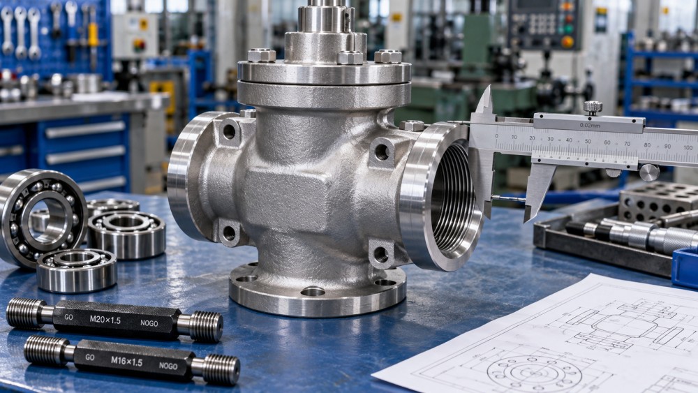
A useful inspection image should show the component from several angles, with arrows identifying measurement references, residual markings, mounting features, and interfaces. Include a scale reference, but do not rely on photographs alone for critical dimensions.
Bearings: match the internal specification, not just the envelope
For rolling bearings, start with bore diameter, outside diameter, and width. Identify the broad construction: deep-groove ball, angular-contact ball, cylindrical roller, tapered roller, or another type. Note whether the assembly is separable and whether it uses shields, contact seals, or an open arrangement.
Then investigate details hidden behind apparently identical dimensions:
- Internal clearance or preload requirements.
- Precision class and runout requirements.
- Cage construction and material.
- Seal design, lubricant, and operating temperature limits.
- Matched-set arrangements and installation orientation.
A standard bearing and a higher-clearance variant may share the same basic dimensions. The correct choice depends on shaft and housing fits, thermal conditions, and the original design. Do not select higher clearance simply because the previous bearing ran hot; misalignment, lubrication problems, or an unsuitable fit may be responsible.
For plain bearings and bushings, geometry is only part of the identification. Base material, lining, lubrication method, and permissible load-speed conditions matter. A bronze bushing is not automatically equivalent to a visually similar composite-lined product.
Power transmission: identify the profile and the operating duty
For a belt drive, inspect surviving belt markings and measure the pulley groove or tooth profile. Determine whether the drive uses V-belts, synchronous belts, or another construction. Width and approximate length are insufficient: belt profiles with similar dimensions can require different pulleys.
Be explicit about length conventions. Inside, outside, pitch, and effective length are not interchangeable. A worn or stretched belt may provide only an approximate starting point, so check catalog definitions and the available center-distance adjustment.
For roller chains, record pitch across several links, roller diameter, inner width, strand count, and connecting-link construction. Wear increases measured chain length. Compare findings with the relevant standard and inspect sprocket geometry; chains with the same nominal pitch can still differ in other dimensions.
Gears require tooth count, face width, bore, keyway or spline details, and an assessment of tooth form. Outside diameter alone does not uniquely determine module or diametral pitch. Pressure angle, helix angle, backlash, material, and heat treatment may need drawings or specialist measurement.
With couplings, check both hubs, the flexible element, shaft retention, and spacing. Confirm torque capacity, speed, and allowable misalignment from documented product data. Matching bolt holes does not prove that an elastomer insert or replacement hub belongs to the same rated assembly.
Fluid control: external similarity is particularly misleading
Start with the component’s role in the circuit. Is the valve controlling direction, pressure, flow, or load holding? Use the schematic and hose routing as evidence, while checking whether field modifications have changed the original arrangement.
Identify port threads by thread diameter, pitch, taper, and sealing method. Similar-looking metric, BSP, and NPT connections are not interchangeable. A connection that starts threading together is not proof of compatibility; incorrect combinations can leak or damage the port.
For valves, establish the number of ports and positions, actuation method, de-energized state, and required spool or poppet function. A directional valve may fit the same manifold while having a different center condition, changing how the actuator behaves when control power is removed.
For pumps, investigate rotation direction, shaft interface, mounting flange, displacement, pressure capability, and allowable speed. Flange dimensions cannot establish displacement. Do not test an unidentified unit by progressively increasing pressure until it “seems adequate.”
Seal compatibility also requires evidence. Fluid type, additives, temperature, and cleaning chemicals can affect suitability. Neither seal color nor housing appearance reliably identifies the elastomer grade.
Observed operating pressure is not the component’s rated pressure. A gauge reading does not capture every transient, and a relief setting does not establish the ratings of all connected parts.
Turn candidate matches into a defensible replacement decision
Catalog searching becomes more efficient once the evidence is organized. Filter by component family and dimensional envelope, then compare function, duty, and compatibility. Keep a shortlist rather than selecting the first item with matching measurements.
Use three labels on the worksheet: verified, inferred, and unknown. This makes uncertainty visible to the technician, supplier, and approving engineer.
For example, a bearing’s measured envelope may match a catalog series, while its internal clearance remains unknown because the suffix is unreadable. The useful conclusion is not “bearing identified.” It is “dimensional family identified; clearance and seal arrangement require confirmation.” That distinction can prevent an avoidable repeat failure.
Send suppliers or manufacturers a complete evidence pack:
- Machine identification, component location, and installation photographs.
- All surviving markings, including ambiguous characters.
- A dimensioned sketch with units and measurement uncertainty where relevant.
- Operating conditions, fluid or lubricant details, and failure symptoms.
- The proposed candidate and the exact specifications still unresolved.
Ask for a documented cross-reference or application assessment, not only a statement that the part “should fit.” Where the original manufacturer is unavailable, qualified engineering review may be needed to specify a replacement independently.
GPCM’s precision-focused approach treats a component as part of a powertrain or fluid-control system, rather than an isolated catalog item. Technical intelligence can help maintenance teams interpret bearing designations, transmission standards, material differences, and supplier documentation. It cannot replace model-specific rating evidence or site-level approval.
Know when identification must stop short of approval
Escalate unresolved specifications for components involved in braking, lifting, load holding, pressure containment, hazardous-area service, or safety functions. The same applies when material, rated capacity, or required certification cannot be established. Production pressure is not a substitute for evidence.
Keep diagnosis separate from identification, too. A correct replacement can fail again if contamination, shaft damage, misalignment, lubrication starvation, or pressure surges remain uncorrected. Record the failure condition before cleaning away evidence.
After replacement approval, inspect mating surfaces, verify installation settings, and follow the manufacturer’s commissioning procedure. Monitor relevant indicators such as leakage, temperature, vibration, pressure, and abnormal noise against documented acceptance criteria. A short successful run does not validate an unknown load or pressure rating.
Finally, update the maintenance record with the approved part number, full designation, supporting documents, photographs, and remaining limitations. Add a durable identifier where appropriate. The best outcome is not merely getting the machine running—it is making sure the next technician does not have to solve the same missing-nameplate problem again.
Related News
- Can distributors profit from low-volume private label components?Oct 20, 2026Explore private label component solutions for distributors to turn low-volume demand into profit. Learn how to control costs, qualify suppliers, and launch a range with confidence.
- How to control design changes when working with an OEM supplierOct 18, 2026Working with an OEM cooperation supplier? Learn how to control design changes, align approvals, verify revisions, and prevent costly production errors with a practical change-control workflow.
- How to vet North American fluid dynamics engineering firms for CFDOct 13, 2026Searching for fluid dynamics engineering North America? Discover how to vet CFD firms, assess validation, and choose a partner for confident design decisions.
- How to identify component specifications when the nameplate is missingOct 20, 2026Learn how to identify component specifications when a nameplate is missing. Use measurements, markings, and records to verify replacement options, avoid costly errors, and reduce downtime.
Related News
- 00
0000-00
Can distributors profit from low-volume private label components? - 00
0000-00
Can fluid power systems for robotics deliver precise motion control? - 00
0000-00
How to control design changes when working with an OEM supplier - 00
0000-00
When do precision ground gears reduce noise in high-speed gearboxes? - 00
0000-00
How pressure ratings affect the price of flow control components
Dr. Alistair Vaughn
Strategic Intelligence Center