








A guide rail that appears straight on a bench can still produce tight spots, uneven carriage resistance, or alignment problems after installation. Straightness errors may increase friction and wear, but similar symptoms can also come from mounting distortion or misaligned parallel rails. A factory’s inspection evidence must distinguish the component’s geometry from the effects of its support and assembly.
An industrial guide components factory should provide a drawing-linked straightness inspection covering the specified surface lines or axis, the required length and directions, defined support conditions, a suitable measurement method, and traceable results. A pass/fail certificate alone is insufficient: acceptance depends on what was measured, how the part was held, and whether measurement uncertainty supports the decision.
Start with the drawing: which straightness is being controlled?
“Rail straightness” is not a complete inspection requirement. A guide component may have a mounting face, a reference side, running surfaces, or a cylindrical shaft axis. Each feature requires a different extraction and evaluation approach. Before approving an inspection plan, identify the feature controlled by the drawing and the applicable geometric tolerancing convention, such as ISO GPS or ASME Y14.5.
Surface-line straightness controls the form of an individual line element on a surface. Its tolerance zone is typically between two parallel lines. One measured line does not establish that the entire face is flat, nor does it prove that another running surface is correctly aligned.
Axis or derived median-line straightness concerns a feature of size, such as a shaft. A cylindrical tolerance zone may be specified. Checking one trace along the shaft’s outside surface is not equivalent to evaluating its derived axis because roundness, taper, and other surface errors can affect that trace.
Straightness is a form control and ordinarily does not require a datum. Nevertheless, the inspection setup needs a defined coordinate system and alignment procedure. Those setup references must not silently convert straightness into parallelism, or let software remove genuine curvature through an inappropriate alignment.
- Identify the controlled feature, drawing revision, tolerance, and evaluation length.
- Confirm whether the requirement applies over the full length, a local length, or both.
- Specify measurement directions and the number and position of traces or sections.
- Resolve any free-state, restrained-state, or material-condition requirements before testing.
Cover the length and directions that can hide defects
Long guides can bow vertically, sweep sideways, or contain localized deviations near ends and mounting holes. A factory should measure the directions required by the drawing rather than report whichever direction gives the smallest result. For a rectangular rail, this may involve longitudinal traces on both the mounting face and reference side. These remain separate feature evaluations unless the specification defines otherwise.
Full-length measurement detects overall curvature, while local-length assessment can reveal a short kink that a global result alone may not adequately describe. Where both limits apply, report both. Do not substitute several short measurements for a full-length result without a validated method for connecting them.
Sampling density matters. Widely spaced readings can miss localized damage or machining waviness. The inspection plan should state the measurement spacing or scanning density, including any additional checks around transitions, joints, or suspect areas. End exclusions also need justification: unmeasured ends may be exactly where a carriage enters a rail or crosses a joint.
For cylindrical guides, inspect enough circumferential and longitudinal information to evaluate the specified feature. Measurements at several orientations can help investigate bending, but the supplier must explain how those readings support the required axis evaluation rather than merely label them “shaft straightness.”
Choose a method that measures the intended feature
No single instrument suits every guide length, stiffness, surface finish, and tolerance. The factory should demonstrate that its method has adequate range, repeatability, and uncertainty for the requirement. Instrument resolution alone does not establish measurement capability.
A precision straightedge with feeler gauges can identify obvious gaps, but it is not automatically suitable for tight acceptance limits. Likewise, rolling a shaft on a bench is a screening exercise, not a traceable axis-straightness assessment.
Rotating a shaft between centers or on V-blocks while recording indicator movement also requires care. The reading can combine bending, eccentricity, roundness error, center condition, and support effects. A total indicator reading should not be presented as pure straightness unless the method separates or appropriately accounts for those influences.
Support and mounting conditions can change the answer
A slender shaft or long rail deflects under its own weight. Moving supports, changing orientation, or applying clamps can change the measured profile without changing the manufactured part. The report should therefore identify support locations, contact arrangement, orientation, and any applied restraint.
Supports should be selected for the component’s geometry and the drawing’s inspection condition. There is no universal support spacing that eliminates sag for every guide. Where gravity compensation is used, the calculation and its assumptions need validation; an undocumented correction can conceal an actual defect.
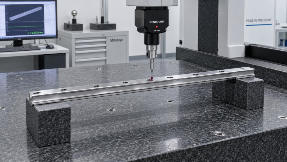
Free-state and mounted-state checks answer different questions. A free-state check assesses geometry under the prescribed support conditions. A mounted-state check shows how the guide behaves when restrained against a defined base. Some rail specifications intentionally rely on mounting to establish the required installed geometry, so neither state should be assumed without checking the specification.
For mounted inspection, record the base’s relevant geometry, locating arrangement, fastener sequence, and tightening conditions. Excessive clamping can pull a bowed rail into apparent compliance or introduce distortion. A result obtained on an undocumented fixture cannot establish how the guide will behave on the receiving machine.
Control temperature, cleanliness, and measurement force
Inspection should follow thermal stabilization of the component, fixture, and measuring equipment. Uniform temperature changes mainly affect dimensions, while temperature gradients can bend a guide and alter its straightness. A part brought directly from grinding, washing, or a different storage environment may not be ready for acceptance measurement.
The procedure should define the permitted environment and stabilization criteria, then record conditions relevant to the test. Long optical measurements also need protection from air movement and thermal gradients along the beam path. Where temperature compensation is applied, the report should make that clear.
Clean contact surfaces before inspection and examine them for burrs, dents, coating buildup, or trapped debris. A particle beneath a support can tilt the rail; contamination beneath a probe can create a false peak. Record any authorized deburring or preparation that changes the inspected condition.
Contact force deserves particular attention on slender shafts and thin profiles. Probe pressure, fixture preload, and repeated handling can deflect the part. Repeated measurements after unloading and reseating help reveal whether a result depends more on setup than component geometry.
Make the calculation and acceptance rule visible
The reported straightness value depends on how the measured data are evaluated. For a surface line, minimum-zone evaluation seeks the smallest separation between two parallel lines enclosing the extracted profile. A least-squares reference line uses a different criterion and can produce a different reported value. The factory should identify its calculation method and show that it matches the applicable requirement.
Axis evaluation likewise needs a defined extraction and association procedure. Software settings are part of the inspection method, not administrative details. Filtering, smoothing, outlier removal, and endpoint exclusion can alter the result, especially where a small localized deviation is important.
Request a profile plot alongside the final value. It helps distinguish a gradual bow from a sharp discontinuity and makes unexplained data gaps easier to notice. Retain raw or exportable measurement data where required for review, while avoiding acceptance rules invented after seeing the result.
Measurement uncertainty should include relevant contributions from the instrument, reference, setup, temperature, sampling, and repeatability. Agree on the conformity decision rule before testing, including any guard band. When a result is close to the tolerance limit, neither an unqualified pass nor an automatic rejection is justified without applying that rule.
Specify an inspection record that can be reviewed later
A usable factory report connects the measured geometry to the actual delivered component. Request the following information in the purchasing or quality agreement rather than waiting until a shipment is disputed:
- Traceability: part number, drawing revision, serial or lot identification, inspection date, and inspector or responsible function.
- Requirement: controlled feature, tolerance, units, evaluated length, directions, and applicable inspection condition.
- Setup: component orientation, support positions, restraints, mounting details where relevant, and environmental conditions.
- Measurement system: instrument identification, calibration status, reference artifact where used, sampling strategy, and evaluation software or method.
- Results: measured deviation, profile or sectional data, required local-length results, and repeatability evidence where needed.
- Acceptance basis: relevant uncertainty, agreed decision rule, disposition, and any deviations from the approved procedure.
Calibration records support instrument traceability, but they do not prove that the complete setup is capable. For demanding tolerances, request method validation, reseating studies, or comparison with an independent measurement approach. These checks are especially useful when introducing a new component length or fixture.
When the factory result and machine behavior disagree
Begin by comparing inspection conditions. A rail measured horizontally on supports cannot be directly compared with one bolted vertically to an imperfect machine bed. Confirm the same feature, length, orientation, evaluation method, and restraint condition before deciding that either measurement is wrong.
Then separate component acceptance from assembly verification. Installed checks may need to cover rail-to-rail parallelism, mounting-face flatness, joint alignment, carriage preload, and travel resistance. Those tests can explain tight spots, but they do not replace the component’s specified straightness inspection.
Quarantine disputed components when uncertainty or setup differences could change the acceptance decision. Preserve the original data and inspect the support and mounting interfaces before attempting straightening or rework. For equipment where binding could affect controlled motion, continued operation requires an engineering assessment of the actual mechanism; a satisfactory straightness report alone is not proof of safe machine operation.
Related News
- When do precision ground gears reduce noise in high-speed gearboxes?Oct 17, 2026Precision ground gears can reduce high-speed gearbox noise when flank errors drive mesh excitation. Discover how optimized geometry and controlled testing verify quieter performance.
- How to choose gear materials for high-load industrial gearboxesOct 15, 2026Choose gear materials for high-load industrial gearboxes with confidence. Compare steel grades, heat treatments, and quality checks to reduce failures and improve service life.
- How to choose engineering plastics for gears without lubricationOct 14, 2026Choose engineering plastics for gears without lubrication. Compare POM, PA and PEEK, assess wear and heat, and discover how to validate reliable dry-running performance.
- What straightness checks should a guide component factory provide?Oct 18, 2026What should an industrial guide components factory prove? Discover essential straightness checks, support conditions, and traceable reports to verify quality before you buy.
Related News
- 00
0000-00
How to control design changes when working with an OEM supplier - 00
0000-00
When do precision ground gears reduce noise in high-speed gearboxes? - 00
0000-00
How pressure ratings affect the price of flow control components - 00
0000-00
How to choose gear materials for high-load industrial gearboxes - 00
0000-00
How to choose engineering plastics for gears without lubrication
Tribology Specialist
Strategic Intelligence Center